Table of Contents
Advertisement
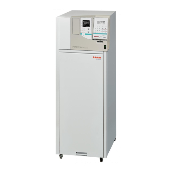
Highly Dynamic Temperature Control Systems
• with integrated programmer
LH 47
air cooled
LH 50
water cooled
JULABO WEST
2575 Pioneer Avenue, Suite 102
Vista, CA 92081
(760) 842-8010
(760) 842-8015
info @ julabo.com
www.julabo.com
19532790.doc
Operating Manual
JULABO EAST
754 Roble Road, Suite 180
Allentown, PA 18109
(610) 231-0250
(610) 231-0260
info @ julabo.com
www.julabo.com
Print date: 15.09.09
Advertisement
Table of Contents

Subscribe to Our Youtube Channel
Related Manuals for Julabo Presto Plus LH 47


Summary of Contents for Julabo Presto Plus LH 47
- Page 1 JULABO WEST JULABO EAST 2575 Pioneer Avenue, Suite 102 754 Roble Road, Suite 180 Vista, CA 92081 Allentown, PA 18109 (760) 842-8010 (610) 231-0250 (760) 842-8015 (610) 231-0260 info @ julabo.com info @ julabo.com www.julabo.com www.julabo.com 19532790.doc Print date: 15.09.09...
- Page 2 Congratulations! You have made an excellent choice. JULABO thanks you for the trust you have placed in us. This operating manual has been designed to help you gain an understanding of the operation and possible applications of our circulators. For optimal utilization of all functions, we recommend that you thoroughly study this manual prior to beginning operation.
-
Page 3: Table Of Contents
TABLE OF CONTENTS OPERATING MANUAL ....................... 5 INTENDED USE ....................5 1.1. Description......................5 OPERATOR RESPONSIBILITY – SAFETY INSTRUCTIONS ......5 2.1. Disposal......................... 7 2.2. Technical specifications..................8 2.3. Cooling water connection ..................12 OPERATING INSTRUCTIONS ..................13 SAFETY NOTES FOR THE USER..............13 3.1. - Page 4 8.1. Configuration ....................... 42 8.2. Control parameters....................45 8.3. Start of a profile ....................47 8.3.1. Interrupting a profile..................49 8.4. Integrated programmer..................50 8.5. Analog inputs/outputs ..................53 8.6. Limits ........................56 8.7. Interface....................... 56 8.8. Sensors ....................... 57 8.9.
-
Page 5: Operating Manual
Operating manual Intended use JULABO Temperature Systems have been designed for temperature application to specific fluids in a external closed system (oop circuit). The units feature pump connections for temperature control of external systems (loop circuit). JULABO circulators are not suitable for direct temperature control of foods, semi-luxury foods and tobacco, or pharmaceutical and medical products. - Page 6 Vista, CA 92081 Allentown, PA 18109 (760) 842-8010 (610) 231-0250 (760) 842-8015 (610) 231-0260 info @ julabo.com info @ julabo.com www.julabo.com www.julabo.com Safety instructions for the operator: Avoid strikes to the housing, vibrations, damage to the operating-element panel (keypad, display), and contamination.
-
Page 7: Disposal
Warning label W26: Colors: yellow, black Hot surface warning. (The label is put on by JULABO) Observe the instructions in the manuals for instruments of a different make that you connect to the circulator, particularly the corresponding safety instructions. Also observe the pin assignment of plugs and technical specifications of the products. -
Page 8: Technical Specifications
Operator responsibility – Safety instructions 2.2. Technical specifications LH 47 LH 50 Mains power connection 360-440V/3PNPE/50Hz 360-440V/3PNPE/50Hz 400 V/3P/50 Hz Current input (at 230 V) Working temperature range °C -47 ... 250 -50 ... 250 Temperature stability ±0.01 ... ±0.05 ±0.01 ... - Page 9 LH 47 LH 50 Mains power connection V / Hz 207-253V/3PPE/60Hz 207-253V/3PPE/60Hz 230 V/3P/60 Hz Current input (at 230 V) Working temperature range °C -47 ... 250 -50 ... 250 Temperature stability ±0.01 ... ±0.05 ±0.01 ... ±0.05 Cooling capacity °C 200 100// 20 0 -20 -40...
- Page 10 Operator responsibility – Safety instructions Temperature selection digital via Removable control module RD indication on DIALOG-Display (LCD) remote control via personal computer indication on monitor Temperature indication VFD-Info-Display DIALOG-DISPLAY (LCD) Resolution 0.01 from -9.99 °C to +249.99 °C Pump pressure display on VFD-Info-Display in five grades Liquid level display on VFD-Info-Display in five grades...
- Page 11 E n v i r o n m e n t a l c o n d i t i o n s a c c o r d i n g t o I E C 6 1 0 1 0 - 1 : •...
-
Page 12: Cooling Water Connection
Operator responsibility – Safety instructions 2.3. Cooling water connection Cooling water pressure (IN / OUT ) max. 6 bar Difference pressure (IN - OUT ) 3.5 to 6 bar Cooling water temperature <20 °C Notice: Cooling water circuit Risk of oil leaking from the refrigeration system (compressor) of the recirculating cooler into the cooling water in case of a fault in the cooling water circuit! Observe the laws and regulations of the water distribution company valid in the location where the unit is operated. -
Page 13: Operating Instructions
Operating instructions Safety notes for the user 3.1. Explanation of safety notes In addition to the safety warnings listed above, warnings are posted throughout the manual. These warnings are designated by an exclamation mark inside an equilateral triangle. “Warning of a dangerous situation (Attention! Please follow the documentation).”... - Page 14 Safety notes for the user • Pay attention to the thermal expansion of bath oil during heating to avoid overflowing of the fluid. • Prevent water from penetrating into the hot bath oil. • Do not drain the bath fluid while it is hot! Check the temperature of the bath fluid prior to draining (by switching the unit on for a short moment for example).
- Page 15 The following questions shall help to recognize possible dangers and to reduce the risks to a minimum. • Are all tubes and electrical cables connected and installed? Note: sharp edges, hot surfaces in operation, moving machine parts, etc. • Do dangerous steams or gases arise when heating? Is an exhaust needed when working? •...
-
Page 16: Operating Controls And Functional Elements
Operating controls and functional elements Operating controls and functional elements Front view LH47 LH50 air-cooled water-cooled... - Page 17 Mains power switch, illuminated Local operating board Socket board - description see page 18 Removable control module RD Filling funnel (hinged) Motor protection circuit breaker for compressor motor 2 Mains circuit breakers (resettable) 10 A for the pump-motor 4 Mains circuit breakers (resettable) 16 A Venting grid, removable Drain with drain port Local operating board...
- Page 18 Operating controls and functional elements Key to swap line 3 on the VFD Identification no. of control module RD Capacity in % E xxx.xx or I xxx.xx Actual value (external or internal) x.xx Pump pressure in bar Key to swap line 1 on the VFD Actual value Int or Ext alternating with line 3 S 120 .00 E 120 .00...
- Page 19 Control module RD DIALOG-DISPLAY (LCD) Standard indication Line 1: Setpoint in °C Setp: 120.00°C IntAct 21.00°C Line 2: Internal actual value in °C ExtAct: 20.00°C Line 3: External actual value in °C Control: Intern Line 4: Control type: internal / external control Indicating messages (e.
- Page 20 Operating controls and functional elements Rear...
- Page 21 Control connector 230 V / max. 0.1 A 4 Mains circuit breakers (resettable) 16 A F1 and F3 Compressor F2 and F4 Heater, Pump Motor protection circuit breaker for compressor motor Mains power cable with plug 13 + 14 Pump connectors Return Feed M16x1...
-
Page 22: The Presto Plus Principle With Closed External System
Operating controls and functional elements 4.1. The Presto Plus principle with closed external system e.g. LH47; double-sided glass vessel Operating: The operation of the temperature system and the indication is effected via the local control panel (2) and the removable operating device RD(4). -
Page 23: Preparations
Fire or other dangers when using bath fluids that are not recommended: Please contact JULABO before using other than recommended bath liquids. JULABO assumes no liability for damage caused by the selection of an unsuitable bath fluid. Unsuitable bath fluids are fluids which, e.g., •... - Page 24 Preparations Diagram 1: JULABO Thermal oils Change in volume in dependence on the temperature of bath liquid. Example A: Filling quantity at ambient temperature 5 liters Intended working temperature range -40 °C bis +250 °C Change in volume caused by temperature 1,75 liters Here an external expansion vessel is required (Order no.: 8 970 830)
-
Page 25: Tubing
5.2. Tubing Recommended tubing: Metal tubing, triple insulated, M16x1, Temperature range -100 °C ... +350 °C Order No. Length 8 930 209 0.5 m 8 930 210 1.0 m 8 930 211 1.5 m 8 930 214 3.0 m Metal tubing, insulated, M16x1, Temperature range -50 °C ... +200 °C Order No. -
Page 26: Installation
Preparations 5.3. Installation Caution: Danger of tipping • Lift the unit only with a crane using the lifting strands and the wooden crate (see pictures on page 2) • The recessed grips on the side are not suited for lifting the unit! Careful positioning of the unit on its rollers is permitted. - Page 27 Caution: Securely attach all tubing to prevent slipping. Connecting the external system: • Remove the cap nuts from the pump connectors (13, 14) and using tubing connect the external system (M16x1 / wrench 19 mm). To prevent the formation of bubbles in the loop circuit, the pressure line (13) is to be connected to the lower nozzle of the external system.
-
Page 28: Cooling Water Connection Lh 50
Preparations Notice: If an expansion vessel is not used, make sure the connector (16) is closed with a cap nut. If an external expansion vessel is mounted later, a part of the bath liquid should be drained before (see chapter Emptying on page 33). It might be helpful to put the castors at the back on a base which is approximately 10-15 mm high. -
Page 29: Power Connection
5.6. Power connection Caution: • Only connect the unit to a power socket with earthing contact (PE – protective earth)! • The power supply plug serves as a safe disconnecting device from the line and must be always easily accessible. •... -
Page 30: Filling Of External, Closed Systems
Preparations 5.7.1. Filling of external, closed systems Section 1 • Connect the unit to a mains power socket (see page 29) and ALARM turn on the unit with the mains power switch (1). CODE 14 During the self-test all segments of the VFD-Info-Display, all control indicators and the DIALOG-DISPLAY light up. - Page 31 Notice: In the >Mode< > fill < or. >drain<>SELECT SYSTEM< is shown when starting. The message >SELECT SYSTEM<is a demand to make an adjustment in the menu >Pump<. The insertion is effected cyclicly until the adjustment has been made. Adjusting Mode: Notice concerning the filling The temperature system was emptied last, therefore the menu option >Mode<...
-
Page 32: Degasifying
Preparations 5.8. Degasifying If the temperature system is operated an automatic degasifying is carried out after the start. During the degasifying unwelcome components of the bath liquid are are drawn off . Examples: Air bubbles which were enclosed in the bath liquid during the filling for the unit. -
Page 33: Draining
5.9. Draining Notice: • Do not drain the bath fluid while it is hot or cold ! Check the temperature of the bath fluid prior to draining (by switching the unit on for a short moment, for example). • Store and dispose the used bath fluid according to the laws for environmental protection. -
Page 34: Operating Procedures
Switching on: • The unit is operated by pressing the mains power switch (1). The integrated pilot lamp illuminates. JULABO During the self-test all segments of the VFD-Info-Display, all P R E S T O control indicators and the DIALOG-DISPLAY light up. -
Page 35: Manual Operation
Manual operation 7.1. Start - Stop Start: Setp.: 20.00°C IntAct 21.00°C • Press the start/stop key ExtAct: --.--°C Control: Intern The actual bath temperature is displayed. For approx. 3 seconds the VFD-Info-Display shows the adjusted >Mode< . 20.00 x.xx → CLOSED SYSTEM Adjustment >... -
Page 36: Direct Setting Of The Working Temperature
Manual operation 7.2. Direct setting of the working temperature This setting may be carried out with the temperature system being Setp.: 20.00°C in operating state Start or Stop! IntAct 21.00°C ExtAct: --.--°C • The value previously set appears on the DIALOG-DISPLAY Control: Intern (LCD) (example: 20.00 °C). -
Page 37: Warning Functions
7.3.2. Warning functions The high and low temperature warning functions accompany the )) )) )) working temperature value. An audible signal sounds in intervals when the actual temperature exceeds one of the set limits (patented). The corresponding message appears in line 4 on the DIALOG- DISPLAY (LCD). -
Page 38: Setting The Pump Pressure Stage
Manual operation 7.3.3. Setting the pump pressure stage The pressure of the circulation pump is adjustable in five grades. After setting, the VFD-Info-Display indicates the corresponding value. >St.Pump: Setting the pump pressure stage Setp.: 120.00°C Setting in line 4. Overt.:130.00°C The value previously set appears on the DIALOG-DISPLAY Subtmp:110.00°C (LCD). - Page 39 Safety temperature in the internal reservoir >RES< This supplementary safety installation supervises and controls the temperature of the bath liquid in the internal reservoir. • Press the key to indicate the safety temperature value in line 3 >RES< on the VFD-Info-Display and using a screwdriver simultaneously turn the setting screw to the desired value (example: 100 °C).
-
Page 40: Internal / External Control
Menu functions 7.5. Internal / external control The temperature system offers the possibility of internal temperature control in the internal bath or external control directly in an external system. Setup for external control: ® Connect a Pt100 sensor to the socket "EXT" of the Presto temperature system, if necessary perform a calibration using the ext. -
Page 42: Configuration
Menu functions 8.1. Configuration By means of the configuration functions, operation of the instrument can be optimized for the current application. • Press enter to select the configuration submenu. • Use the up/down cursor keys to select the desired option. A flashing line indicates that a value needs to be entered. - Page 43 >Autostart Note: The temperature system has been configured and supplied by JULABO according to N.A.M.U.R. recommendations. This means for the start mode, that the unit must enter a safe operating state after a power failure (non-automatic start mode). This safe operating state is indicated by "OFF", resp. on the VFD-Info-Display.
- Page 44 Menu functions Should such a safety standard not be required, the AUTOSTART function (automatic start mode) may be activated, thus allowing the start of the instrument directly by pressing the mains power switch or using a timer. Possible parameters: on - AUTOSTART on off - AUTOSTART off Warning For supervised or unsupervised operation with the AUTOSTART function, avoid...
-
Page 45: Control Parameters
8.2. Control parameters When performing an identification for the controlled system (temperature applications system) (see page 42), the control parameters Xp, Tn, Tv and Xpu will be automatically determined and stored. Each parameter may be manually set via the keypad if necessary, to allow optimum control performance. - Page 46 Menu functions >DynInt< - Dynamics This parameter affects the march of temperature only in case of internal control (see page 40) Adjustable parameter: standard The temperature rises quicker, however can overshoot up to 5 %. If a ramp is defined, the march of temperature often follows this ramp.
-
Page 47: Start Of A Profile
8.3. Start of a profile The start menu of the integrated programmer allows calling up and defined starting of one of six previously stored temperature profiles. The profiles are started manually or via the integrated timer. There are two possibilities for manually starting a program: 1. - Page 48 Menu functions • When selecting the parameter time, a new menu level is called up for entry of the start time. A flashing segment indicates that a start time needs to be entered. Example: hour.min 6:00 h hour.min Start time Day.Mon day and month Year...
-
Page 49: Interrupting A Profile
8.3.1. Interrupting a profile Interrupting a profile: • Press the start/stop key to interrupt or continue a profile. The setpoint and time period set for the corresponding section are thus stopped at the values presently achieved. The instrument is put on hold and the message "pause" flashes on the DIALOG DISPLAY (LCD). -
Page 50: Integrated Programmer
Menu functions 8.4. Integrated programmer The integrated programmer allows any desired temperature program sequences to be realized. Such a temperature sequence is called profile. A profile consists of individual sections defined by duration (t:) and target temperature. Target temperature is the setpoint (T:), that is achieved at the end of a section. - Page 51 Edit Compile profiles: • A flashing segment indicates that a number needs to be entered. Under submenu "Edit Profile" enter a profile number. Six profiles may be stored (nos. 0 to 5). Examples: • Then programme the desired values for each section. Profile No 1: Use the keypad to set section number, target temperature and time period.
- Page 52 Menu functions Delete • A flashing segment indicates that the respective profile number needs to be entered in which one or more consecutive sections are to be deleted. • In lines 2 and 3 of the DIALOG DISPLAY (LCD) enter the numbers of the sections to be deleted.
-
Page 53: Analog Inputs/Outputs
8.5. Analog inputs/outputs This submenu enables setting of the input and output values for the programmer input and the temperature recorder outputs of socket REG+E-PROG (21). • Press enter to select the inputs/outputs submenu. • Use the up/down cursor keys to select the desired option and press enter to open. - Page 54 Menu functions Examples: lowest temperature value: 10 °C highest temperature value 210 °C 10 °C 210 °C Fig. shows 200 °C scaled to paper width Δ Τ = 200 K rise: 50 mV/°C 197 °C 202 °C Δ Τ = 5 K lowest temperature value: 197 °C highest temperature value:...
- Page 55 Example: • Set the external voltage or current source output for the equivalent of 50 °C temperature setpoint. The value adjusted and set on the external programmer is displayed in line 4 of the DIALOG-DISPLAY (LCD) for control purposes (Example: ExtSet: 50.0 °C). After returning the LCD display to standard display by pressing the temperature value adjusted and set on the external voltage or current source is displayed in line 1...
-
Page 56: Limits
Menu functions 8.6. Limits The limits IntMax and IntMin are only valid under external control (see 7.5. Internal / external control). They restrict the temperature of the internal bath to the desired maximum/minimum, also if the controller would require a higher/lower temperature for the external system. -
Page 57: Sensors
8.8. Sensors ATC - Absolute Temperature Calibration • Select the submenu "Temp.Sensor" with enter • Select the desired option with the up/down cursor keys A flashing digit indicates that a value needs to be entered i.e. set. ATC Int: internal sensor ATC Ext: external sensor •... -
Page 58: Pump
Menu functions 8.9. Pump In this submenu the circulation pump can be turned on separately, without heating element or cooling unit. The menu option „Modus“ refers to the filling valve and the ventilation valve. Depending on the operating status (drain / fill / sys close) the valves are switched off automatically. -
Page 59: Troubleshooting Guide / Error Messages
" illuminates and a continuous signal tone sounds. CODE 14 Defect temperature sensor in refrigeration circuit. CODE 02 Repair by authorized JULABO service personnel. Cable of the working temperature sensor interrupted or short-circuited. CODE 05 Defect of the working or safety temperature sensor. - Page 60 • After eliminating the malfunction, press the mains power switch off and on again to cancel the alarm state. If the unit cannot be returned to operation, contact an authorized JULABO service station. Disturbances that are not indicated.
-
Page 61: Electrical Connections
10. Electrical connections Important: Use shielded cables only. The shield of the connecting cable is electrically connected to the plug housing. RS232/RS485 serial interface (3.5) This port can be used to connect a computer with an RS232 or RS485 cable for remote control of the temperature system. SERIAL Pin assignments: RS232 Pin 2... - Page 62 Electrical connections Programmer input / temperature recorder output (3.1) Analog inputs / outputs see page 53 Signal 1 Voltage output Channel 1 0 ... 10 V 2 Voltage output Channel 2 0 ... 10 V 3 GND for outputs REG+E-PROG 4 Programmer input EPROG 0 to 10 V / 0 to 20 mA...
- Page 63 Stand-by input (3.2) (for external emergency switch-off) Pin assignment: Signal not connected 5 V / DC Use shielded cables only. Activate the stand-by input: • Under menu item Stand-by, set the parameter to "yes" (see page 44). • Connect an external contact 'AK' (e.g. for emergency switch-off) or STAND-BY an alarm contact of the superordinated system.
-
Page 64: Remote Control
Remote control Connector for removable control module RD (3.6) Extension cable for operating device RD: Order No. 8 980 126 2 m long Order No. 8 980 127 5 m long Control connector (10) Output voltage is applied when the unit runs, for example after pressing the start/stop key Output voltage: 230 V∼... -
Page 65: Communication With A Pc Or A Superordinated Data System
11.2. Communication with a PC or a superordinated data system Suitable terminal programs for communicating with a PC are: • MS-Windows - TERMINAL.EXE (included with MS-Windows). If the temperature system is put into remote control mode via the configuration level, the display will read "R -OFF-"... -
Page 66: List Of Commands
Remote control 11.3. List of commands When the RS485 interface is used, the instrument address stands in front of each command (Axxx_). in commands: Asking for parameters or temperature values to be displayed. Command Parameter Response of instrument version none Number of software version (V X.xx) status none... - Page 67 Command Parameter Response of instrument in_mode_05 none Temperature system in Stop/Start condition: 0 = Stop 1 = Start in_mode_08 none Adjusted control dynamics 0 = aperiodic 1 = standard in_par_01 none Time constant of the external bath. in_par_02 none Internal slope. in_par_03 none Time constant of the internal bath.
- Page 68 Remote control Command Parameter Response of instrument out_mode_02 Continual identification of controlled system whenever a new setpoint is to be reached. out_mode_04 Temperature control of internal bath. External control with Pt100 sensor. out_mode_04 out_mode_05 Stop the unit = R –OFF-. out_mode_05 Start the unit.
-
Page 69: Status Messages / Error Messages
11.4. Status messages / error messages The instrument sends data (including error messages) only when the computer sends a query. Status messages Description 00 MANUAL STOP Presto in "OFF" state. 01 MANUAL START Presto in keypad control mode 01 MANUAL START,DEGASING Presto in keypad control mode and degasifying active 02 REMOTE STOP Presto in "r OFF"... -
Page 70: Cleaning The Unit
Clean the outside of the unit using a wet cloth and low surface tension water (e.g., soap suds). Before applying a cleaning or decontamination method different from the one recommended by JULABO, the user has to make sure with the manufacturer, that the planned method does not damage the unit. - Page 71 Caution: • Choose the detergent according to the bath liquid which is used. E.g. Ethanol, Silicon remover can be used. • Take care the room where cleaning takes place is well ventilated. • Set the working temperature setpoint. 20.00 Recommendation: 20 °C Cleaning the inside: If you change the bath liquid or want to use a different one, carefully clean the parts in contact with the bath...
- Page 72 Cleaning the unit Cleaning is performed in two steps. First rinse the internal reservoir, the tubing lines and the heat exchanger. As second step, carefully remove the cleaning liquid. 1. Cleaning internal reservoir, tubing lines and heat exchanger: • Fill the temperature system with cleaning liquid. See chapter 5.7.
-
Page 73: Maintaining / Repairing The Unit
13. Maintaining / repairing the unit Caution: Always turn off the unit and disconnect the mains cable from the power source before cleaning the unit. Prevent humidity from entering into the circulator. Electrical connections and any other work must be performed by qualified personnel only. - Page 74 The unit is designed for continuous operation under normal conditions. Periodic maintenance is not required. Repairs Before asking for a service technician or returning a JULABO instrument for repair, please contact an authorized JULABO service station. When returning the unit: •...
-
Page 75: Warranty Provisions
14. WARRANTY PROVISIONS The following Warranty Provisions shall apply to products sold in North America by Julabo (“Seller”) to the entity shown as buyer (“Buyer”) on Seller’s invoice. Initial Warranty. Upon Seller’s receipt of payment in full for the products and subject to Buyer’s... - Page 76 WARRANTY PROVISIONS INCIDENTAL OR CONSEQUENTIAL DAMAGES TO BUYER OR ANY THIRD PARTY AND ALL SUCH DAMAGES ARE HEREBY DISCLAIMED. Assignment. Buyer shall not assign any of its rights or obligations hereunder without the prior written approval of Seller; provided, however, that if Buyer is a distributor of Seller, the rights and obligations of Buyer under these Warranty Provisions shall inure to the benefit of and be binding upon Buyer’s customers who provide the product’s proof of purchase to Seller pursuant to the terms set forth herein.
Need help?
Do you have a question about the Presto Plus LH 47 and is the answer not in the manual?
Questions and answers