Table of Contents
Advertisement
Advertisement
Table of Contents

Related Manuals for CBD-Tech ChiTu L M1

Summary of Contents for CBD-Tech ChiTu L M1
- Page 1 ChiTu L M1 Manual CBD-Tech...
- Page 2 This user manual includes but is not limited to all the information contained in it. It is protected by copyright law. Without the permission of Shenzhen CBD-Tech Co., Ltd. ("CBD-Tech"), it may not be arbitrarily copied, translated or other uses.
- Page 3 The user knows that CBD-Tech has the right to modify this manual at any time. Once the product specifications or drivers are changed, this manual will be updated accordingly. For detailed instructions on updating this user manual, please visit the official website: http://www.cbd-3d.com...
-
Page 4: Table Of Contents
Menu Menu ............................3 Safety Information ........................4 About this user manual ......................5 Packing list ..........................7 Specification list ........................8 Summary ..........................9 Read first ..........................9 Standby power LED ......................10 1.1 Controller board overview ....................11 1.2 Controller board Layout .................... -
Page 5: Safety Information
Safety Information Electrical safety • To avoid possible electric shock and serious damage, please unplug the power cord of the printer or controller board from the power socket before any operation. • When you want to add a hardware device to the system or remove the hardware device from the system, be sure to connect the cable of the device before connecting the power cord. -
Page 6: About This User Manual
About this user manual The product manual contains all the information you need when installing the CBD-Tech ChiTu L M1 series controller board. User manual layout The user manual is composed of the following chapters: Chapter 1: Introduction to the hardware structure ... - Page 7 Where to find more information You can get the product information you use and the update information of software and hardware through the two channels provided below. 1. CBD-Tech website You can go to official website: http://www.cbd-3d.com to get all kinds of information about ChiTu Systems products.
-
Page 8: Packing List
Packing list Please check the package once you get it, whether all the item listed below are complete. Item Description Controller Board ChiTu L M1 Series Touch Screen 2.8/3.5/4.3/5.0/7.0 inch FFC Cable 0.5-40 FFC Others User manual、Connector If any of the accessories listed above are damaged or missing, contact your dealer as soon as ... -
Page 9: Specification List
Specification list Basic Model ChiTu L M1 Information Time to market 2020 Size*(mm) 120 * 85 * 20 Weight(g) Touch Screen Size(inch) 2.8/3.5/4.3/5.0/7.0 Supported Panel(inch) Tianma-TM089CFSP01(8.9 inch 4K Mono) Parameter Microprocessor Chip ARM STM32F4 Series Information Stepper Motor Chip Trinamic TMC2209... -
Page 10: Summary
Summary Read first The integrated circuits of board are easily damaged by static electricity. Be sure to make the following precautions before you change any setting: Before installing the controller board, please put it in an anti-static mat or anti-static bag. ... -
Page 11: Standby Power Led
Standby power LED The controller board comes with a standby power LED that lights up to indicate that the system is ON, in sleep mode,or in soft-off mode. This is a reminder that you should shut down the system and unplug the power cable before removing or plugging in any controller board component. -
Page 12: Controller Board Overview
1.1 Controller board overview 1.1.1 Screw holes Place 4 screws into the holes indicated by circles to secure the controller board to the chassis. Confidential 11 / 73 2020/06/28... -
Page 13: Controller Board Layout
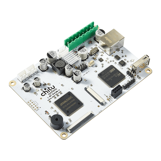
1.2 Controller board Layout Name Name Ethernet port Heat sink Reset button Mainboard fan port ARM STM32F4 series CPU UV LED fan port USB 2.0 port UV LED port External motor driver pin Power supply Z motor driver pin TFT resistive touch screen ANOLOGIC EL2F series FPGA chip LCD resin panel Buzzer... -
Page 14: Component Overview
1.3 Component overview 1.3.1 Power supply This port is for power supply for the entire controller board. 1.3.2 UV LED This port is for control and signals the LED light device connected. 1.3.3 UV LED fan This port is for control and signals the LED light fan device connected. 1.3.4 Mainboard fan This port is for control and signals the mainboard fan connected. - Page 15 1.3.6 Z+ end stop This port is for control and signals the Z-axis maximum end stop connected. Pin Name/Pin Tag Number Definition Description +(VCC) Power Output Z+ Endstop (Maximum position) -(GND) (Z+) Signal pin 1.3.7 Z- end stop This port is for control and signals the Z-axis minimum end stop connected. Pin Name/Pin Tag Number Definition...
- Page 16 1.3.10 LCD resin panel (MIPI port) This port is for control and signals the LCD panel connected. 1.3.11 TFT Resistive touch screen This port is for control and signals the resistive touch screen port connected. 1.3.12 USB 2.0 This port is for read the USB 2.0 connected. 1.3.13 Buzzer This component will emit a "beep"...
-
Page 17: Installation Flow
Installation Flow 2.1 Installation overview Confidential 16 / 73 2020/06/28... -
Page 18: Regular Installation
2.2 Regular installation 2.2.1 Installing power supply As shown below, connect the power supply wire with“-12V/24V+”port. As shown below, the arrow shows the where “-12V/24V+”on the board. Confidential 17 / 73 2020/06/28... - Page 19 2.2.2 Installing touch screen (TFT Resistive) As shown following steps, connect the touch screen cable (FFC cable). ①、Find the screen connector on the board As shown below, “U13”on the board. ②、Pull out the black bar As shown on ②, put your finger on each side of the black bar(mark as red), pull out the bar to follow the arrow direction, as shown on ③.
- Page 20 ③、Insert the FFC cable As shown below, put the FFC cable pin side towards up, stiffeners shielded side(usually the blue side) towards down, make sure to insert the cable all the way till it can’t move forward anymore. ④、Close the black bar back As shown on ②, put your finger on each side of the black bar(mark as red), push back the bar to follow the arrow direction, as shown on ③.
- Page 21 ⑤、Connect the touch screen Use the same way to connect the rest side of FFC cable with touch screen, on the contrary, stiffeners shielded side towards up and pin side toward down as usual. ⑥、Installing finished Confidential 20 / 73 2020/06/28...
- Page 22 2.2.3 Installing the LCD panel (printing screen) As shown following steps, connect the LCD panel cable(printing screen), as shown “J6”on the board. ①、Find the LCD panel connector As shown below, the “J6” on the controller board. ②、Open the cover of the connector As shown below, put your thumbs on the cover and open it lightly.
- Page 23 ③、Insert the LCD panel cable. Put the stiffeners shielded side (usually dark brown color) towards up, pin side towards the board, make sure to insert the cable all the way till it can’t move forward anymore. ④、Close the cover of the connector As shown below, press the cover slowly to close the connector.
- Page 24 2.2.4 Installing UV LED light Insert the 2 pins of the UV LED light into “-LED+”on the controller board, you can also install different light source as your demand. ①、COB + Reflective Cup ②、Parallel LED array As shown below, the “-LED+”on the controller board. Confidential 23 / 73 2020/06/28...
- Page 25 2.2.5 Installing UV LED fan Insert the 2 pins of the UV LED light fan into “-LED_F+” on the controller board. As shown below, the “-LED_F+” on the controller board. Confidential 24 / 73 2020/06/28...
- Page 26 2.2.6 Installing controller board fan Insert the 2 pins of the controller board fan into “-MB_F+”on the controller board. As shown below, “-MB_F+” on the controller board. Confidential 25 / 73 2020/06/28...
- Page 27 2.2.7 Installing Z stepper motor Insert the 4 pins of the z stepper motor into “Z_MOTOR” on the controller board. As shown below, the “Z_MOTOR” on the controller board. Confidential 26 / 73 2020/06/28...
- Page 28 2.2.8 Installing Z-axis minimum end stop Insert the 3 pins of the Z-axis minimum end stop into“Z-”on the controller board. As shown below, “Z-”on the controller board. Confidential 27 / 73 2020/06/28...
-
Page 29: Firmware Update
2.4.1 Firmware file format overview The following table shows several common files in the firmware update process. You can visit the official website of CBD-Tech (www.cbd-3d.com) to get the firmware version corresponding to the controller board and download. 文件名 描述... - Page 30 2.4.2 Firmware update process A) Check the current firmware version Open the 3d printer, click the“system”of the main page, you will enter the“system”page. In the“system”page, click the“Information, you will enter“Information”page. In the“Information”page, the info after is the current firmware version. Confidential 29 / 73 2020/06/28...
- Page 31 B) Check the compatible board firmware Please check the compatible firmware of your board on the official website www.cbd-3d.com, can check info according to your board or ask customer support. C) Download the firmware files Download the corresponding firmware base on your controller board. You can download it to your PC or laptop.
- Page 32 G) Update other files Click“Print”you will enter“file list”page In this page you can see all the files and folders in the U disk. choose the firmware you want to update, you will enter“file info”page. Confidential 31 / 73 2020/06/28...
- Page 33 In“file info”page, print the file by clicking button, the printer will read the file and start upgrade automatically. During the updating, please DO NOT click any button in case of updating failed. There will emit twice a "beep" sound to remind you of the completion of firmware updating. Restart the printer to check.
-
Page 34: User Guide
User guide 3.1 Function list The firmware program mainly provides four major functional modules include file management, printing control, component calibration, and system settings. Description Page Functional modules U disk read 43-44 File list display 43-44 File management File deleted 46-47 File preview Local printing... -
Page 35: Icon Overview
3.2 Icon overview Description of common icons in the firmware program Icon Description Usage Back Back to last page Start Start printing a file, or continue the file printing process Delete Delete a file Stop Stop printing process Pause Pause the printing process of the current model Setting Enter to the settings page In the file list page, click to view the list file on the previous page... -
Page 36: Page Structure
3.3 Page structure Confidential 35 / 73 2020/06/28... -
Page 37: Page Description
3.4 Page description 3.4.1 Main page The first page after controller board start working Tool: enter “Tool” page System: enter “System” page Print: enter “Print” page 3.4.2 Tool page Include exposure test, component calibration etc. Manual: Enter “Move Z axis” page Exposure: Enter “Exposure testing”... - Page 38 3.4.3 Move Z axis page Move Z(printing plate) with different distance by manual ①: Unselected value unit of stepping travel ②: Unselected value unit of stepping travel ③: Reset the platform to default height you set. ④: Move Z up, Z axis will move up the current value unit you choose. ⑤: Move Z down, Z axis will move down the current value unit you choose.
- Page 39 3.4.5 Clean exposure time setting page Exposure time setting for clean the resin vat Tag ①: exposure time, is an integer, unit second and default setting is 200s, click to enter “parameter input” page. Tag ②:increase“exposure time”, add one second every click. Tag ③:decrease“exposure time”, cut one second every click.
- Page 40 3.4.7 File list page list the file and folders from local or U disk Tag ①:Back to upper page, click to exit the current folder and return to upper page. Tag ②:Enter to new folder, click to enter the folder. Tag ③:Model or files, click to enter “file info”...
- Page 41 3.4.9 Printing process page Display the detailed information during printing, include slicing images, layers, printing time etc, at the same time you can pause, stop or enter setting page. Tag ①: Slicing image currently printed; Tag ②: File name currently printed; Tag ③:...
- Page 42 3.4.10 Printing setting Display the core parameter in this printing file, such as bottom layers; exposure time etc. Bottom layers: the bottom layers during the printing process, click to enter “parameter input” page. Bottom exposure time: the bottom layer exposure time during the printing, click to enter “parameter input”...
- Page 43 3.4.12 System page Include all the function except core function. Such as system info, after sale etc. Information page: Click to enter “information” page Network: click to enter “Network” page Service: click to enter “Service” page Language: click to “language” page Calibration: click to “calibration”...
- Page 44 3.4.14 Service page The official after sale and tech support information. Confidential 43 / 73 2020/06/28...
-
Page 45: Function Guider
3.5 Function guider 3.5.1 Read U disk A) Insert U disk Insert the U disk include printing file into the printer. B) Click “Print” Click the “Print” button on the main page, enter “file list” page. C) Check U disk file list On this page, you can view the list of files and folders in the current U disk. - Page 46 When you have not inserted a USB flash drive, this page displays a blank list. Confidential 45 / 73 2020/06/28...
- Page 47 3.5.2 Model preview A) Click “Print” Click the “Print” button on the main page, enter “file list” page. B) Choose model file Choose one of the models with the file format can be previewed, enter “file info” page. Note: the file can’t be previewed if the format not support preview. C)...
- Page 48 3.5.3 Delete file A) Click “Print” Click the “Print”button on the main page, enter“file list”page. B) Choose model file In this page, you can choose the file you want to delete. C) Choose model file Choose the file you want to delete. Confidential 47 / 73 2020/06/28...
- Page 49 D) Click “delete” button In this page, you can click the in the right side, there will be a box to confirm if delete or not. E) Click “Confirm” Click “Confirm”, the file will be deleted Click “Cancel” .the box will be closed. Confidential 48 / 73 2020/06/28...
- Page 50 3.5.4 Local printing method Flow of local printing: Detailed steps for local printing: A) Click “Print” Click the “Print” button on the main page, enter “file list” page. B) Enter “File list” page In this page, you can choose the file you want to print. Confidential 49 / 73 2020/06/28...
- Page 51 C) Choose a model file Choose a model file you want to print. D) Enter “File info” page In this page you can preview the 3D file. E) Click “Print” button Click the in the right side, then start printing. Confidential 50 / 73 2020/06/28...
- Page 52 3.5.5 Printing control (Pause/Resume/Stop) A) Pause printing In “Printing process” page, click the button in the right side, printing will pause, and Z axis will move up to default setting height. B) Resume printing In “Printing process” page, click the button in the right side, printing will start again from the last layer to finish the print file.
- Page 53 C) Stop printing In “Printing process” page, click the button in the right side, there will be a box to confirm if stop or not. Click “Cancel”, the printing will continue. Click “Confirm”, the printing will stop and exit the page. Confidential 52 / 73 2020/06/28...
- Page 54 3.5.6 Network printing Flow of network printing: Detailed steps for network printing: A) Open CHITUBOX software Open the CHITUBOX in your PC or laptop. B) Import STL file Open file or drag the file to CHITUBOX. Confidential 53 / 73 2020/06/28...
- Page 55 C) Settings Click “Settings”, make sure use the “default” mode. D) Click “Slice” After settings, click “Slice” and wait the slicing process to complete. E) Click “Network sending” After slicing, click “Network sending” in the right side. Confidential 54 / 73 2020/06/28...
- Page 56 F) Send file In “Network sending” box, click “Printer name” list, select the printer or board that connected to the LAN, click , the file will send to the printer. Confidential 55 / 73 2020/06/28...
- Page 57 3.5.7 Printing setting Flow of printing setting: Detailed steps for printing setting: A) “Printing process” page The printing setting can only edit when the file is printing. B) Click “Printing setting” button In “printing process” page, click the button in the right side to enter “printing setting”. Confidential 56 / 73 2020/06/28...
- Page 58 C) Enter “Printing setting” page For now, you can edit 4 parameters, bottom layer count, bottom exposure time, exposure time and light-off delay. D) Choose the parameter to set. Click the parameter, enter the “Parameter input page” E) Enter “Parameter input page” Confidential 57 / 73 2020/06/28...
- Page 59 F) Keyboard input area Input the number value on keyboard input area G) Click “Save” button After input, click button in the right side to save. Confidential 58 / 73 2020/06/28...
- Page 60 3.5.8 Resin tank clean Flow of resin tank cleaning: Detailed steps for resin tank cleaning: A) Click “Tool” button Click the “Tool” button on the main page B) Click “Clean” button Click “Tool” button, enter “Clean exposure time setting” page. Confidential 59 / 73 2020/06/28...
- Page 61 C) Set exposure time parameter In this page, you can adjust the time by button, or click “Parameter input” page to input by manual. D) Click “Next” After input the parameter, click “Next” to enter “Exposure process” page. E) Enter “Clean process” page Wait the process finish.
- Page 62 3.5.9 Exposure test Flow of exposure testing: Detailed steps for exposure testing: A) Click “Tool” button Click the “Tool” button on the main page. B) Click “Exposure” Click “Exposure” button, enter the “Exposure” page. Confidential 61 / 73 2020/06/28...
- Page 63 C) Set exposure time parameter In this page, you can adjust the time by button, or click “Parameter input” page to input by manual. D) Click “Next” After input the parameter, click “Next” to enter “Exposure process” page. E) Enter “Clean process” page Wait the process finish.
- Page 64 3.5.10 Z platform reset A) Click “Tool” button Click the“Tool”button on the main page. B) Enter “Tool” page C) Click “Manual” button Click “Manual” button to enter the “Manual” page. Confidential 63 / 73 2020/06/28...
- Page 65 D) Click “Home” button Click button, the Z platform will automatically move to the default height. Confidential 64 / 73 2020/06/28...
- Page 66 3.5.11 Control the Z platform Flow of controlling the Z platform: Detailed steps for controlling the Z platform: A) Click “Tool” button Click the “Tool” button on the main page B) Click “Manual” button Click “Manual” button to enter “Manual” page. Confidential 65 / 73 2020/06/28...
- Page 67 C) Enter “Manual” page D) Set stepper value Set the stepper value for up or down. E) Click “Up” or “Down” button Click button, Z axis will move Up/down the current value unit you choose Confidential 66 / 73 2020/06/28...
- Page 68 3.5.12 Language Switch Flow of language switching: Detailed steps for language switching: A) Click “System” button Click “System” button in the main page. B) Enter “System” page Confidential 67 / 73 2020/06/28...
- Page 69 C) Click “Language” button Click “Language” button, there will be a “Language switched” box. D) Click “Confirm” button Confidential 68 / 73 2020/06/28...
- Page 70 3.5.13 Beep on/off Flow of turning on/off the beep: Detailed steps for turning on/off the beep: A) Click “System” button Click “System” button on the main page. B) Enter “System” page C) Click “Info” button Confidential 69 / 73 2020/06/28...
- Page 71 D) Enter “Info” page E) Click “Beep” button means beep on status, click to switch to , The system will enter the sound off mode. means beep off status, click to switch to , The system will enter the sound on mode. Confidential 70 / 73 2020/06/28...
- Page 72 3.5.14 Information A) Click “System” button Click “System” button on the main page. B) Click “Info” button Click “Info” button on the System page. C) Enter “Info” page This page you can the key information of board. The series and model number of this controller board.
- Page 73 3.5.15 Service A) Click “System” button B) Click “Service” button Enter “System” page, click “Service” button C) Enter“Service”page The official after sale and tech support information. Confidential 72 / 73 2020/06/28...
-
Page 74: Others
Address : Room 409, Block A, Huafeng Smart Innovation Port, Gushu 2nd Road, Xixiang Street, Baoan District, Shenzhen Tel : (+86) 0755-23103569 Official website : www.cbd-3d.com E-mail : sales@cbd-3d.com E-mail : support@cbd-3d.com Contact us: Official Facebook Channel CBD-Tech Link address QR code https://www.facebook.com/CBD3D Official Facebook Group ChiTu https://www.facebook.com/groups/ Channel...
Need help?
Do you have a question about the ChiTu L M1 and is the answer not in the manual?
Questions and answers