
Related Manuals for CBD-Tech Chitu V3.6

Summary of Contents for CBD-Tech Chitu V3.6
- Page 1 Chitu V3.6 User Manual Compiler:Pitt Xie Date 01/11/2015 Reviewer:David Yi Date: 01/11/2015 Approver:Sam Lin Date: 01/11/2015...
-
Page 2: Copyright Declaration
TEL: +860755-23103569 Official website : www.cbd-3d.com EMAIL: sales@cbd-3d.com QQ: 2056288869 If you have any technical problems, please visit CBD-Tech technical ) and download the information forum(http://www.cbd-3d.com/forum/ you need. - Page 3 PC, offering you a platform to show your company. This system is bilingual and can be switched between Chinese and English by one button. CBD-Tech can provide the services for different languages. 1.1 Parameters of Mainboard...
-
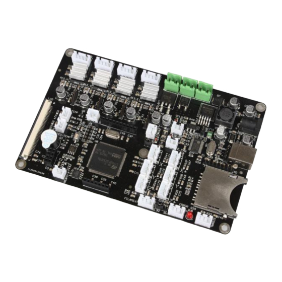
Page 4: Interface Layout
1.2 Interface Layout Single-head Mainboard Stepping Motor 12-24V X Axis Y Axis Z Axis E1 Axis supply 5V/12-24V Jumper Power adapter Power adapter Power adapter E-Temp Board fan 24V Light bar End fan 2.8 inch or 3.5 inch X-min X-max Light Interface of B-Temp... -
Page 5: Expansion Interface
Double-head Mainboard Stepping Motor 12-24V X Axis Y Axis Z Axis E1 Axis supply 5V/12-24V Jumper Power adapter E-Temp Board fan 24V Light bar End fan 2.8 inch or X-min X-max Light 3.5 inch Interface of B-Temp SD Slot Y-min Y-max color touch screen... -
Page 6: How To Use
2.How to Use Firmware Parameters Setting Open the file of Complete machine parameters V1.2.30.gcode ( the one with the notepad icon with file ending .gcode)with notepad. Set the related parameter in line with machine parameters, which is shown as follows. Click to “save”... - Page 7 Update Firmware in SD Card Plug the jumper cap of 5V/12-24V, supplying for USB. There are two kinds of power supply. USB(5V) Power Supply Power Supply(12-24V)...
- Page 8 Choose one of the above methods. Take USB supply as example, plug the jumper cap and connect screen flat cable. The screen will light up. After the SD card is plugged, choose the file of Complete machine parameters V1.2.30.gcode and print. When printing is finished(about 2s-3s), the firmware parameter is updated, shown as following figure.
- Page 9 Computer Test Printing After the connection of all the external devices, plug the jumper cap of 12-24V, which is shown as follows. If you use a power adapter, the interface switch needs to be configured, as seen below. If you use the power adapter, the switch can be connected in both holes.
- Page 10 3.FAQ 1.Why does not the screen light up after the connection and plugging of USB or power supply? Answer: ⑴ Wrong connection of power supply jumper cap. ⑵ Poor contact of flat cable on both sides of screen. It is recommended to pull out and plug again.
- Page 11 5.How to adjust the drive current of the drive chip? Answer: At present, the driving chip current is calculated by I=U/0.8 (driving voltage divided by 0.8), the factory default is 0.85V, the driving (rotary potentiometer) voltage is the highest recommendation does not exceed 1.1V (driving chip current is too high to force the cooling), the following describes how to measure the driving voltage, as shown below.
Need help?
Do you have a question about the Chitu V3.6 and is the answer not in the manual?
Questions and answers
Hello, I downloaded a wrong firmware to my chitu 3.6 board and now it dopes not work! How can I revert it to the factory firmware ?