
Related Manuals for Karassn KS-858G

Summary of Contents for Karassn KS-858G
- Page 1 PSTN&GSM/GPRS Alarm System User Manual AC PWR RESET...
-
Page 2: Table Of Contents
Contents 1.System Introduction-------------------------------------------------------------------------------------- 1 2.Main Functions -------------------------------------------------------------------------------------------- 1 3.System Diagram ------------------------------------------------------------------------------------------- 2 4.System Installation --------------------------------------------------------------------------------------- 3 5.Keypad Programming Instructions --------------------------------------------------------------------- 7 Directive 00: Set/modify installer code ---------------------------------------------------------------- 7 Directive 01-09: Set/modify user's code/master code ---------------------------------------------- 8 Directive 10-14: Set common telephone number ---------------------------------------------------- 8 Directive 15-19: Set zone list to dial corresponding telephone number when alarming ------ 9 Directive 20: Set dialing mode -------------------------------------------------------------------------- 9 Directive 21: Set telephone communication protocol ----------------------------------------------- 9... -
Page 3: System Introduction
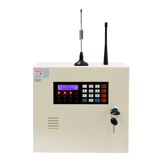
The list of standard full kit 1.Alarm host 2.Key 2pcs 3.Remote controller 2pcs 4.Radio antenna 5.GSM antenna 6. Double-end telephone line 7.2.2KΩline end Resistance 8pcs 8. Screw 2pcs 9.Self tapping Screw 3pcs 10. Plastic Bolt 3pcs 11.User's Manual 12. Power lead 1.Introduction This is a Telephone&GSM/GPRS dual networking Alarm system with LCD display and 4*4 keyboard, and there are 16 zones (8 wireless zones and 8 wired zones). -
Page 4: System Diagram
2.18 Linkage with wired/wireless Siren 2.19 Latest 30 pieces of alarm record (Alarm information, Month/Day/hour/minute) can be recorded, and the user and time of the last arm time and the last disarm time can be recorded. If the records are over 30 pieces, then it will delete the preceding ones automatically. -
Page 5: System Installation
4.System Installation Thank you for choosing our products! As you known, any kinds of products, to assure its credibility and fully display all its functions, it should be installed and used correctly. So we recommend installing by professional personnel. Otherwise, we will not be responsible for malfunctions caused by improper installing or use. - Page 6 Wireless Transceiver Volume Button Module Battery SMA Connector Black Battery Anti-tamper is only effective Pluggable Module when connecting interfaces BELL C SW C AUX C AC AC Z1 C Z2 Z3 C Z4 Z5 C Z6 Z7 C Z8 NC NO COM PHONE LINE TAMPER C Programmable Tamper Outputting Interface...
- Page 7 4.2.5 Backup battery connection To make sure alarm host will work normally in case the AC cut off, the alarm host should be connected with storage battery as picture 1. Connecting the red line to the anode, and connecting the black line to the cathode.
- Page 8 Connection picture 2. Wired zone line-connection diagram Normal Open End/ Normal Close Normal Open End with resistance Normal Close End with resistance End without resistance Line-connection Line-connection Line-connection ends of alarm host ends of alarm host ends of alarm host A U X 2.2K +12V GND...
-
Page 9: Keypad Programming Instructions
5. Keypad Programming Instructions 5.1 Preprogramming instructions 1). Program mode [ ] [ ] [ ] [SET] + [CODE] + [OK] + [Program Directive] + [OK ]+ Directive Index Reset Note: [SET] + [CODE ] + [OK ]is used to enter program state. [SET] + [Installer's Code] + [OK ]is used to enter installer program state. -
Page 10: Directive 01-09: Set/Modify User's Code/Master Code
Directive 01-09: Set and modify user code/master code In installer or master program state: Press[01 ]+[ OK ]+[ users code 4 digits ]+[users code 4 digits]+ [OK ] to set the 1 user code Press[02 ]+[OK ]+[ users code 4 digits ]+[users code 4 digits]+ [OK ] to set the 2 user code Press[03 ]+[... -
Page 11: Directive 15-19: Set Zone List To Dial Corresponding Telephone Number When Alarming
No stored phone numbers by default Directive 15-19: Set zone list to dial corresponding telephone number when alarming How to set self-test report function In installer program state Press [ 15] +[ OK ] +[appointed zone no.] +[OK ]to set appointed zones to dial the 1 alarm phone number. -
Page 12: Directive 24: Set Ademco Accounts
Directive 24: Set ADEMCO account In installer program state, Press[24]+[OK ] +[Account 4 digits]+[OK ] Note: when networking with ADEMCO center, the code should be 4 bits (0000-9999) No account by default Directive 26: Set wireless siren In installer program state, Press [26]+[OK ]... -
Page 13: Directive 32: Set Circuit Type For Wired Zone
Code Wired zone respond time 50ms 2 (default) 100ms 250ms 500ms 750ms 100ms for all wired zones by default Directive 32: Set wired zone type In installer program state, Press[32]+[OK ] +[xxxxxxxx]+[OK ], X is wired zoned type for zone 1 to 8. X value see table below Code Name Wired zone type... -
Page 14: Directive 35: Set Linkage Alarm Duration For Appointed Zones
For instance, If you desire to set zone 2、 4、 6 and phone line malfunction, built-in siren duration is 30 minutes when it alarms, In install program state, Press[34]+[OK ] +[30][ 2 4 6 9] +[ OK] The screen will show as below. Picture 13 Inner siren duration 20 minutes for all zones by default No built-in siren for phone line broken by default... -
Page 15: Directive 37: Set The Second Group Of Arm/Disarm Timer For Zone List
Arm time ranges are 4 digits, 2 digits for hour, 2 digits for minute Disarm time ranges are 4 digits, 2 digits for hour, 2 digits for minute Partition number range is 1、 2……9. (9 is for all partitions) For instance, if you desire to arm at 18:20pm, and disarm at 07:40 am next morning for partition 1, 2 automatically. -
Page 16: Directive 49: Query Device Id Number (Can Not Be Modified)
Picture 17 Directive 49: Query device ID number (Can not be modified) In installer program state, Press[49]+[OK ], the device ID number of the alarm host will automatically displays on the LCD screen.(The device ID number is composed of 12 digits or letters) Directive 50: Record your message In installer program state, Press[50]+[OK ]to enter the record menu, and press [... -
Page 17: Directive 59: Set And Query Heartbreak Time
Directive 59: Set and query heartbreak time In installer program state, Press[59]+[OK ]+[x]+[OK ], x=(10-300)in seconds Directive 60: Register/delete remote controller In installer program state, Press[60]+[OK ]to enter register remote controller menu, and input code number 1 to 8 for corresponding remote controller and[OK ]key to confirm. -
Page 18: Directive 80: Set To Factory Default
For instance, register the third sensor in the second zone. In installer program state, Press[72]+[OK ]to enter the second zone sensor register. Press [ 3]+[OK ] to enter the third code. Picture20 for vacant code, Picture21 for registered code. Picture 18 Picture 19 Register a sensor in a vacant code and trigger it, Bi-Bi-means register successfully. - Page 19 Users Program Definition Default Remark memo Directive Set/delete the 1st alarm phone number Set/delete the 2nd alarm phone number Set/delete the 3rd alarm phone number Set/delete the 4th alarm phone number Set/delete the 5th alarm phone number Set/delete the 1st alarm phone number 12345678 for appointed zones Set/delete the 2nd alarm phone number...
- Page 20 Users Program Definition Remark Default memo Directive Set/delete the 5th partition for appointed zones 12345678 Set/delete the 6th partition for appointed zones 12345678 Set/delete the 7th partition for appointed zones 12345678 Set/delete the 8th partition for appointed zones 12345678 Query device ID number Record message Periodic test Enable/disable forced arm...
-
Page 21: User Operation Instructions
6.Users Operation Instruction 6.1 Panel instruction 1). LED indicator Z1 to Z8 indicators are for zones 1 to 8. All the zone indicator are off in normal state. The zone indicator is on when it detects alarm signals. The zone indicator will be flashing once every 4-second when it is in arm state. - Page 22 Alarm time “ September 15th, 11:38” “N01” is the first alarm record. “Z08” is the 8th zone Antenna Fire means fire alarm. Disarm The screen can be scrolled for more alarm records, Emergency Home Arm (scrolling once every 5 seconds) is Arm Key is Disarm Key is Home Arm Key...
- Page 23 4). Sound indicator Indicator Definition A short “Bi-” Valid indicator for keyboard indicator Two short “Bi-Bi-” Program operation correctly or arm indicator Four short “Bi-Bi-Bi-Bi-” Power on inspect--self or disarm indicator A long “Di----” The wrong program indicator A short “Di-” every second Phone line failure indicator A short “Bi-”...
- Page 24 3) Arm/Disarm through timer. 4) Arm/Disarm through remote telephone with user code or master code. Note: the user code Arm/Disarm is only for corresponding partition. Master coder is for all partitions Note: During Arm operation, the sound “Bi- Bi-”means Arm, the Arm indicator light will be on and the corresponding zone will enter arm state.
- Page 25 If you receive call from alarm host without doing any operations. It will display message 5 times repeatedly and dial next phone number. When using the GPRS module to dial the alarm call, press 4# on the phone or mobile phone to enter the two-way audio function (the two-way audio time is 10 minutes, and other valid commands can be operated during the period).
-
Page 26: App Programming Instructions
7.APP Programming Instructions Before using the APP, please make sure that there is GPRS network connection function enabled (directive 56, enabled by default) 7.1 The alarm host installs the SIM card correctly 7.2 Download APP as below: 7.3 Open the APP to register an account. (It can be registered by email address) 7.4 Add alarm host 2) Add new device →... - Page 27 3) Click in the upper right corner to scan the device QR code on the back cover 4) Added successfully of the alarm host. Or manually fill in the device ID number and password 7.5 Alarm host operation instructions Modifiable host name Share device to other APP account Living Room Home arm...
-
Page 28: Main Technical Specification
All programming items can be modified on the system settings menu. Note: "Restore factory default settings" on the APP: Wireless remote controller, detectors and network parameters are not restored, all other recovery. 8.Technical Specification 8.1 Alarm host Size: 26.4cm X 26cm X 8cm (LXWXH) excluding length of antenna Weight: 3KG (Excluding backup battery) Power Supply:AC220V±15%, Battey:12V/7Ah Auxiliary Output Power:<550mA... -
Page 29: Simple Troubleshooting
10. Simple Failure Recovery Fault Express Answer Zone communication failure 1.Check the sensor to see if it If the alarm host does not receive to report works normally. signals from the zone beyond 26 hours, it won't report that the 2.Check the distance between communication is failure. - Page 30 Warning: Limits Of This Safe System 、 As an advanced technical guard system, although it can reduce the occurrence of theft robbery and fire, it can not promise to have no any above-mentioned accidents happens or have no any personnel casualty and property losses happens.
- Page 31 V1.0...
Need help?
Do you have a question about the KS-858G and is the answer not in the manual?
Questions and answers