Table of Contents
Advertisement
Available languages
Available languages
Quick Links
Sierra Ingleteadora Compuesta
Compound Miter Saw
SI810
Manual de Usuario y Garantía.
User's Manual and Warranty.
ATENCIÓN: Lea, entienda y siga las instrucciones de seguridad contenidas en este
manual antes de operar esta herramienta.
WARNING: Read, understand and follow the safety rules in this manual, before operating this tool.
Advertisement
Table of Contents

Related Manuals for Urrea SI810


Summary of Contents for Urrea SI810
- Page 1 Sierra Ingleteadora Compuesta Compound Miter Saw SI810 Manual de Usuario y Garantía. User’s Manual and Warranty. ATENCIÓN: Lea, entienda y siga las instrucciones de seguridad contenidas en este manual antes de operar esta herramienta. WARNING: Read, understand and follow the safety rules in this manual, before operating this tool.
-
Page 2: Table Of Contents
E S P A Ñ O L E N G L I S H CONTENIDO CONTENT Introducción Introduction Normas generales de seguridad General safety rules Seguridad eléctrica Electrical safety Seguridad personal Personal safety Uso y cuidado de la máquina Tool use and care Normas específicas de seguridad Specific safety rules Características... -
Page 3: Introducción
E S P A Ñ O L • M a nua l de U su a ri o Los cables dañados o enredados aumentan el NORMAS GENERALES DE SEGURIDAD riesgo de choque eléctrico. Esta SIERRA DE INGLETE tiene características Cuando maneje una herramienta eléctrica en que harán su trabajo más rápido y fácil. -
Page 4: Uso Y Cuidado De La Máquina
drogas, alcohol o medicamentos. Un momento UTILIZACIÓN Y CUIDADOS DE LAS de distracción mientras maneja herramientas HERRAMIENTAS ELÉCTRICAS eléctricas puede causar un daño personal serio. Use equipo de seguridad. Lleve siempre pro- No fuerce la herramienta eléctrica. Use la he- tección para los ojos. -
Page 5: Normas Específicas De Seguridad
E S P A Ñ O L • M a nua l de U su a ri o SERVICIO de trabajo y un tope de longitud, ambos deben Haga revisar su herramienta eléctrica por un estar instalados en el mismo lado de la mesa servicio de reparación calificado usando sola- de la sierra para evitar que la sierra coja el ex- mente piezas de reemplazo idénticas. - Page 6 place toda pieza dañada, faltante o defectuosa h) Velocidad en vacío. antes de reanudar el trabajo. • SIEMPRE porte la herramienta por el mango • ¡SIEMPRE PERMANEZCA ALERTA! No permi- de acarreo. ta que su familiaridad con la máquina (prove- •...
-
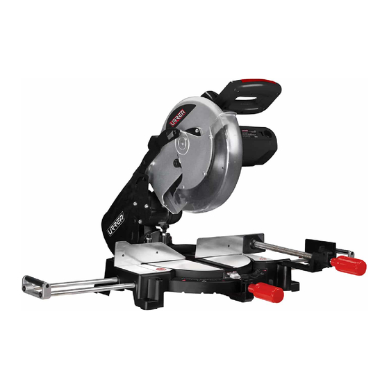
Page 7: Características
E S P A Ñ O L • M a nua l de U su a ri o DESEMPAQUE CARACTERÍSTICAS Desempaque cuidadosamente la sierra de in- CONOZCA SU HERRAMIENTA glete y todas sus partes. No tire el empaque Antes de intentar usar la herramienta lea cui- hasta que haya ensamblado por competo su dadosamente este manual y comprenda todas sierra de inglete. - Page 8 tornillo del ala (3) que sostiene el soporte en da la escuadra del disco. El disco deberá tocar su lugar. completamente la escuadra. 4. Inserte ambos rieles de extensión a través del 2. Si el disco no hace contacto con el largo total primer set de orificios (4) que se encuentran en de la escuadra, ajuste la guía como se mencio- la parte de fuera de la base.
-
Page 9: Instrucciones De Operación
E S P A Ñ O L • M a nua l de U su a ri o AJUSTE DEL TOPE DE BISEL (Fig. 9) sa por encima de la costilla en el puerto. Libere Asegúrese de que el indicador del bisel se ali- las pestañas después de girar la bolsa hasta que nee con la escala a 45º, cuando el mango se el cierre quede hacia abajo. - Page 10 ADVERTENCIA: No cruce sus brazos en fren- Remplace inmediatamente el disco si muestra te del disco mientras este operando la sierra. signos de deterioro o daños. Un disco sin filo o Asegúrese de que los bloqueos del inglete se dañado pueden causar daños personales serios encuentren apretados antes de operar su sierra y causar que el disco no cumpla su función co- de inglete.
-
Page 11: Cortes
E S P A Ñ O L • M a nua l de U su a ri o de 10"(25,4 cm). Verifique que la dirección de rotación del disco coincida con el que indica la • Al cortar tablas o molduras largas, apoye el flecha de rotación que se encuentra en la guar- extremo opuesto del material sobre un sopor- da superior del disco. - Page 12 brazo de la sierra hacia la izquierda al ángulo Para efectuar este tipo de corte, el brazo de de bisel deseado. control de la mesa de ingletes debe girarse al • Los ángulos de bisel pueden fijarse de 0° a ángulo correcto y el brazo de la sierra debe 45°.
- Page 13 E S P A Ñ O L • M a nua l de U su a ri o extremo opuesto del material sobre un sopor- nados. Las dos superficies de contacto de una te de rodillo o con una superficie de trabajo a moldura de corona que queda horizontal con- nivel con la mesa de la sierra.
-
Page 14: Mantenimiento
CÓMO CORTAR MATERIAL IRREGULAR ° CIELO RASO Al cortar material distorsionado, siempre ase- ° gúrese de que esté colocado en la mesa de in- gletes con el lado convexo contra la guía. Si se coloca de una forma equivocada el mate- rial distorsionado, pellizcará... -
Page 15: Especificaciones Técnicas
E S P A Ñ O L • M a nua l de U su a ri o • Vuelva a armar la unidad empleando conjun- ADVERTENCIA: No permita en ningún mo- tos de carbones nuevos. Asegúrese de que la mento que fluidos para frenos, gasolina, pro- curvatura de la carbones corresponda a la del ductos a base de petróleo, aceites penetrantes,... -
Page 16: Tabla De Ajustes De Ángulos
EXTENSION CORDS GENERAL SAFETY RULES Replace damaged cords immediately. The use Your COMPOUND MITER SAW has many fea- of damaged cords can shock, burn or electric tures that will make your job faster and easier. shock. If an extension cord is necessary, a cord Safety, performance and reliability have been with adequate size conductors should be used given top priority in the design of this tool,... -
Page 17: Tool Use And Care
E N G L I S H • U se r’s m a n ua l Before connecting the tool to a power source Keep cutting tools, sharpened and clean. Cut- (receptacle, outlet, etc.) be sure that the volt- ting tools in good condition with sharpened age supplied is the same as that one specified edges, are less likely to stuck in workpieces or on the nameplate of the tool. - Page 18 • NEVER PERFORM ANY OPERATION FREE- performing any work using the saw. HAND. Always place the workpiece to be cut • ALWAYS TURN OFF THE SAW before discon- on the miter table and position it firmly against necting it to avoid accidental starting when re- the fence as a backstop.
-
Page 19: Features
E N G L I S H • U se r’s m a n ua l safe operation and instructing others who may 9. DUST BAG. use this product. 10. CLAMP VISE ASSEMBLY. WARNING: The operation of any power 11. EXTENSION WING ASSEMBLY. tool can result in foreign objects being thrown 12. - Page 20 2. Tilt the saw back to gain access to the under- Avoid touching the saw teeth with the square. side of the base. Secure the saw so that it will The set in the blade’s teeth will hold the square not tip or fall off the workbench.
-
Page 21: Operation Instructions
E N G L I S H • U se r’s m a n ua l BEVEL STOP ADJUSTMENT (Fig. 9) HANDLE STOP LATCH (Fig. 11) Make sure the bevel indicator aligns with the TO RAISE: The saw bevel index 45° mark when the handle assem- should never bly is against the bevel stop screw. - Page 22 If your saw does not have extension wings, use 1. Loosen the guard Fig.13 a support that is the same height as the table. plate screw (1) (Fig. The support must allow the workpiece to lay 13). flat against the table, it must be very stable, 2.
-
Page 23: Cutting With Miter Saw
E N G L I S H • U se r’s m a n ua l MITER CUT (Fig. 18) • Align the indicator point for the desired 1. Unlock the miter angle. handle (1) by turning • Once the saw arm has been set at the desired counterclockwise. - Page 24 Also, each time you adjust the bevel setting • Slowly lower the blade into and through the you change the effect of the miter setting. It workpiece. may take several settings to obtain the desired • Release the switch trigger and allow the saw cut.
- Page 25 E N G L I S H • U se r’s m a n ua l either right or left, depending on the desired Bevel Angle Type of Cut cut for the application. See the chart below for Setting correct angle settings and correct positioning Left side, inside corner of crown molding on miter table.
-
Page 26: Maintenance
• Remove brush cap with a screwdriver. Brush MAINTENANCE assembly is spring loaded and will pop out WARNING: When servicing, use only identi- when you remove brush cap. cal replacement parts. Use of any other parts • Remove brush assembly. may create a hazard or cause product damage. - Page 27 M a n u a l d e u s u a r i o / U s e r ’s m a n u a l CÓMO REALIZAR CORTES COMPUESTOS CUTTING COMPOUND MITERS Como ayuda para realizar los ajustes correc- To aid in making the correct settings, the com- tos, se suministra la siguiente tabla de ángulos pound angle setting chart below has been pro-...
-
Page 28: Garantía
P O L I Z A D E G A R A N T Í A W A R R A N T P O L I C Y Urrea Herramientas Profesionales S.A. de C.V. Urrea Herramientas Profesionales S.A. de C.V.
Need help?
Do you have a question about the SI810 and is the answer not in the manual?
Questions and answers