
Subscribe to Our Youtube Channel
Related Manuals for Refrigeration Innovation Thermo-Simple 2

Summary of Contents for Refrigeration Innovation Thermo-Simple 2
- Page 1 [Thermo‐Simple 2 (TS.2)] 2019 Refrigeration Innovation Thermo‐Simple 2 Manual Refrigeration Innovation 575 Menlo Dr. Suite 5 Rocklin, CA 95648 p.530.666.3020 w.thermosimple.com Page 1 of 12 ...
-
Page 2: Hardware Configurations
[Thermo‐Simple 2 (TS.2)] 2019 HARDWARE CONFIGURATIONS MULTI‐NODE (SPINE) CONFIGURATIONS This configuration allows a single power supply to power up to 6 Thermo‐Simple 1 and/or 2. Power Supply PN: PS‐S-1 Spine Cable – 6 feet PN: Spine‐6 Spine Cable – 13 feet Junction Box (Single Temp.) PN: Spine‐13 PN: ST‐3 Spine Cable – 25 feet PN: Spine‐25 Sensor – 6 feet PN: H3‐6 Power Harness Sensor – 13 feet PN: H3‐13 PN: H2‐S Sensor – 25 feet PN: H3‐25 Display Unit PN: TS2-DS Power Supply for Multi‐Node The power supply for Multi‐Node Configuration is not interchangeable with Single Node power supply. This is due to different load requirements. INPUT OUTPUT Plug type: NEMA 1‐15p Plug type: RJ45 (8 Positions 8 Contacts) Voltage: 100‐240 Vac(50‐60 Hz) Voltage: 12 Vdc Current: 0.2 A Current: 1.5 A Page 2 of 12 ... - Page 3 [Thermo‐Simple 2 (TS.2)] 2019 Junction Box (For Single Temperature Case) There are three RJ45 receptacles. The main power receptacles are the 2 on left and right hand side. The third receptacle on the bottom provides regulated power output for Thermo‐Simple thermometers. NOTE ON JUNCTION BOX CONNECTIONS: DO NOT connect Thermo‐Simple Power harness, H2 harness, into any of the 2 main power receptacles. DO NOT connect Power Supply or Spine cable, into the third output receptacles. For proper connection please refer to the Multi‐Node (Spine) Configuration diagram. SPINE Port: Connect Power Supply or Spine Cable here. WARNING: DO NOT connect H2‐S Power harness in here. Thermo Simple Port: Connect Power harness (H2‐S) here. WARNING: DO NOT connect Power Supply or Spine cable in here. Page 3 of 12 ...
-
Page 4: Power Supply
[Thermo‐Simple 2 (TS.2)] 2019 SINGLE NODE CONFIGURATION Node configuration is suitable for stand alone cases. Power Supply PN: PS‐N-1 Single Temp. Power Harness PN: H2‐N Sensor – 6 feet PN: H3‐6 Dual Temp. Sensor – 13 feet Power Harness PN: H3‐13 PN: H2‐N‐DT Sensor – 25 feet PN: H3‐25 Dual Temp. Input Not available on Single Temp. Power Harness Display Unit PN: TS2‐DS Power Supply INPUT OUTPUT Plug type: NEMA 1‐15p Plug type: Molex 2 Pin Voltage: 100‐240 Vac (50‐60 Hz) Voltage: 12 Vdc Current: 0.2 A Current: 0.35 A Dual temperature Power harness For dual temperature case with Dry Contact switch control. The dual temperature cable wire is orange and white orange. There’s no polarity. The wires connect to the switch in series. With Dual‐Temp power harness the set‐point can be automatically switched between 5.0°F (Low Temperature) and 40.0°F (Medium Temperature) depending on the Dual Temperature switch position on the case. When the switch is open, the set‐point becomes +40.0°F (Medium Temperature). When the switch is close, the set‐point becomes +5.0°F (Low Temperature). Page 4 of 12 ... -
Page 5: Hardware Installation
[Thermo‐Simple 2 (TS.2)] 2019 HARDWARE INSTALLATION HOLES PATTERN Here is the holes dimension to make the cut out. MOUNTING SCREWS Please use #8 pan head self tapping sheet metal screws for mounting. #8 Self Tapping Pan Head Sheet Metal Screws Page 5 of 12 ... -
Page 6: Display Unit
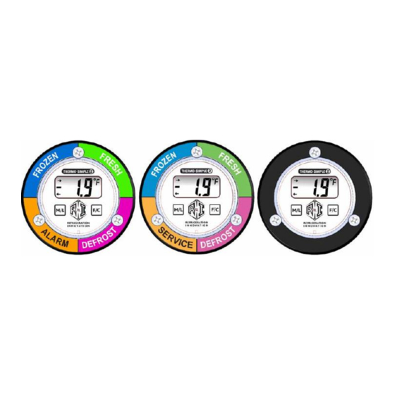
[Thermo‐Simple 2 (TS.2)] 2019 DISPLAY UNIT DISPLAY Incoming Data Indicator (wireless system only) Temperature Scale Positive/Negative Temperature indicator Outgoing Data Indicator Numeral Indicator (wireless system only) (Temperature/Set‐Point/ Device’s Address/Status) TS.2 displays temperature in its default state. It also displays incoming and outgoing communication between the device and the wireless network a wireless system. MAGNETIC SWITCHES Thermo‐Simple 2 /TS.2 Switch Function switch F/C Switch M/L Switch Temp. scale switch Set‐point switch To trigger a magnetic switch on the TS.2 device, a Refrigeration Innovation Magik Wand is needed. The Magik Wand can be purchased from RI to ensure that the switches are triggered properly. In absence of a Magik Wand, the magnetic switches on a TS.2 device can be triggered by any strong magnet (Neodymium rare‐earth type. A typical refrigerator door magnet or whiteboard magnet are NOT strong enough). Page 6 of 12 ... -
Page 7: Features And Functions
[Thermo‐Simple 2 (TS.2)] 2019 FEATURES AND FUNCTIONS The basic switch functions can be used to temporarily change the temperature scale or display the currently active set‐point. There are also arrays of advanced switch sequences to change the default temperature scale, change active set‐points, and obtain or delete the device address in a wireless system. Basic Functions Switch Assignment Description Turn on red LED, display temperature in Centigrade. Temperature automatically reverts back to Fahrenheit in approximately 10 seconds. Temporarily Change F/C Temperature Units If any LEDs are flashing from any previous command, triggering this switch will clear the flashing LEDs and any displayed address on the screen. Note: This will not clear an active Alarm. M/L Display active set‐point Turn on green LED, display current alarm set point temperature. Turn on blue LED. TS.2 switch, this is a function switch which is Thermo‐Simple 2 enabled for 2‐1/2 seconds after triggering. Function/Service Request trigger (TS.2) While the Blue LED is lit, triggering other switches will invoke various advanced functions and settings Page 7 of 12 ... - Page 8 [Thermo‐Simple 2 (TS.2)] 2019 Service Request (Advanced) Functions Switch Assignments Descriptions Sequence From the factory, the default temperature display is Degrees Fahrenheit. Triggering this function will set the default to Degrees Centigrade. Set the default temperature If triggered during a Defrost cycle, this will override the display of ‘dEF’ on TS.2 | F/C display to the opposite of the Display. This allows reading of the actual temperature during a Defrost what is currently displayed cycle. This override will not change the default temperature units and is only in effect for one Defrost cycle. The next Defrost cycle will display ‘dEF’ as normal. While the set‐point is flashing on the display, triggering of the M/L switch will successively change the set point to the next pre‐programmed set point. This will cycle through all the set‐points as long as the display is flashing. Select/Change alarm set‐ TS.2 | M/L Allowing the display to stop flashing will assign the new set point that is point displayed. Note: Setting the “dt” mode for Dual temp cases allows the set‐point to be automatically modified with the case switch between 5°F and 40°F for low and medium temperatures respectively. This toggles Defrost function on or off. When Defrost function is turned on: The display unit will show ‘dEF’ when the case is out of Set‐point temperatures for the first time. F/C | M/L Toggle Defrost On/Off When Defrost function is turned off: The display unit will keep showing temperature when the case is out of Set‐point temperatures for the first time. After the first 60 minutes the unit will go into alarm. TS.2 + TS.2, triggers the Function switch once to light the Blue LED then ...
- Page 9 [Thermo‐Simple 2 (TS.2)] 2019 Clear an assigned address TS.2 + TS.2 + M/L switches will clear any assigned address and cause the and stop device unit to stop responding to commands from the WiDAQ wireless network. communication TS.2 | TS.2 | M/L After the Unit’s address has been cleared, the F/C switch can be triggered WiDAQ (wireless) system to clear the flashing LED and display. only TS.2 + TS.2 + [TS.2 & HOLD], trigger the Function switch once to light the Manually assign the device Blue LED. Trigger it again within 2‐1/2 seconds to light the Green LED. address. Trigger and hold for auto‐increment, or tap until the desired address number is shown. Thermo‐Simple unit MUST NOT have previously The Blue LED will flash briefly and allow the unit to start communicating to TS.2 | TS.2 | [TS.2 assigned address. the WiDAQ wireless network using the manually assigned network & HOLD] address. Previous address number must be cleared first This is intended to allow replacement of a device that already has an address on the WiDAQ network with a new device using that same WiDAQ (wireless) system address. Note: Use of an address that is already assigned to another only device on the network will cause malfunction of both devices. Device Alarm Set‐Point The set‐point configures the device to operate in the range of temperature for that particular case. The set‐point determines whether the case temperature is within range or not and determines when the unit goes into alarm. To View the current Set‐point of a device tap the M/L switch. Hint: Once a switch is tapped pull the magnet at least ½” away from the switch to allow it to turn off. Magnet End To check the current ...
- Page 10 [Thermo‐Simple 2 (TS.2)] 2019 Tap “TS.2” once Magnet End FIRST To change the current Set‐point, tap the M/L switch once, (within 2 seconds of TS.2 Tap “M/L” switch). once only Keep tapping the M/L switch to cycle through the available Set‐points. Stop on the desired Setpoint to set it. Set-Points Each Thermo-Simple has multiple selectable high alert set points. Setpoints are as follows: DT for use with dual temp +0 for use with frozen Ice Cream applications +5 for use with standard frozen applications +36 for use with sensitive fresh meat applications +40 for use with all standard fresh applications...
- Page 11 [Thermo‐Simple 2 (TS.2)] 2019 Magnet End To enable/disable Defrost Notification: Tap the F/C switch once then tap the M/L switch once, (within 1 second of the F/C switch). Tap “F/C” “Off” on display means the Defrost THEN Tap here FIRST state has been disabled. “M/L” “On” on display means the Defrost state has been enabled. Technical Support 530-666-3020 ext 103 Call for support if you have any uncertainty or questions, this will save you time. Troubleshooting Magnet tool required to check and change settings Problem 1.
-
Page 12: Year Warranty
[Thermo‐Simple 2 (TS.2)] 2013 WARRANTY 2‐Year Warranty Thermo‐Simple 2 from Refrigeration Innovation, (the "Product"), is warranted against defects in materials and workmanship under normal use, for a period of 2‐years from the date of purchase. In the event of a product failure due to materials or workmanship, Refrigeration Innovation will repair or replace the defective product. For warranty service, return the defective product to Refrigeration Innovation, shipping prepaid, for prompt repair or replacement. The foregoing sets forth the full extent of Refrigeration Innovation’s warranties regarding the Product. Repair or replacement at Refrigeration Innovation’s option is the exclusive remedy. THIS WARRANTY IS GIVEN IN LIEU OF ALL OTHER WARRANTIES, EXPRESS OR IMPLIED, AND REFRIGERATION INNOVATION SPECIFICALLY DISCLAIMS ALL WARRANTIES OF MERCHANTABILITY OR FITNESS FOR A PARTICULAR PURPOSE. IN NO EVENT SHALL REFRIGERATION INNOVATION, ITS SUPPLIERS OR LICENSORS BE LIABLE FOR DAMAGES IN EXCESS OF THE PURCHASE PRICE OF THE PRODUCT, FOR ANY LOSS OF USE, LOSS OF TIME, INCONVENIENCE, COMMERCIAL LOSS, LOSS OF PRODUCT, LOST PROFITS OR SAVINGS, OR OTHER INCIDENTAL, SPECIAL OR CONSEQUENTIAL DAMAGES ARISING OUT OF THE USE OR INABILITY TO USE THE PRODUCT, TO THE FULL EXTENT SUCH MAY BE DISCLAIMED BY LAW. SOME STATES DO NOT ALLOW THE EXCLUSION OR LIMITATION OF INCIDENTAL OR CONSEQUENTIAL DAMAGES. THEREFORE, THE FOREGOING EXCLUSIONS MAY NOT APPLY IN ALL CASES. This warranty provides specific legal rights. Other rights which vary from state to state may also apply. Page 12 of 12 ...
Need help?
Do you have a question about the Thermo-Simple 2 and is the answer not in the manual?
Questions and answers