Table of Contents
Advertisement
Advertisement
Table of Contents

Related Manuals for Magnum Industrial MI-16300

Summary of Contents for Magnum Industrial MI-16300
- Page 1 MODEL NO.: MI-16300 & MI-16303 OPERATING MANUAL...
-
Page 2: Rules For Safe Operation
RULES for SAFE OPERATION MAGNUM INDUSTRIAL BELT and DISC SANDER To help ensure safe operation, please take a moment to learn the how to operate the machine and understand its applications and limitations, as well as potential hazards. KMS Tools and Equipment disclaims any real or implied warranty and holds itself harmless for any injury that may result from the improper use of its equipment. -
Page 3: Tool Overview
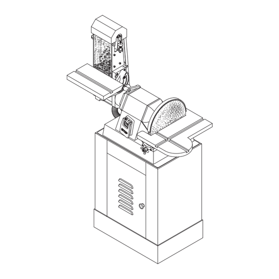
TOOL OVERVIEW MAGNUM INDUSTRIAL BELT and DISC SANDER MAIN COMPONENTS (A) BELT TRACKING ADJUSTMENT (B) SANDING DISC (C) MITRE GAUGE (D) DISC TABLE LOCK KNOB (E) DUST HOSE (F) SANDING BELT (G) BELT GUARD (H) MAIN ON/OFF SWITCH (I) BELT SANDER WORK TABLE... -
Page 4: Additional Requirements
ASSEMBLY INSTRUCTIONS MAGNUM INDUSTRIAL BELT and DISC SANDER • Before you assemble your band saw, review the parts breakdown and keep it ready for reference. • Start by removing the parts from the packaging. • Carefully check the packaging for small pieces before you continue. - Page 5 ASSEMBLY INSTRUCTIONS MAGNUM INDUSTRIAL BELT and DISC SANDER WARNING! This machine is heavy. Ask a friend to help you assemble it. INSTALLING THE SANDING HEAD The sanding mounts onto a base cabinet, which provides storage space for the mitre gauge and replacement sanding discs and belts.
-
Page 6: Basic Adjustments
BASIC ADJUSTMENTS MAGNUM INDUSTRIAL BELT and DISC SANDER WARNING! Serious personal injury could occur if you connect the machine to a power source before you have completed the assembly steps. Do not connect the machine to a power source until instructed to do so. - Page 7 BASIC ADJUSTMENTS MAGNUM INDUSTRIAL BELT and DISC SANDER WARNING! Before making any adjustments ensure the power switch is OFF and the power cord is unplugged ADJUSTING 90° POSITIVE STOP: SANDING DISC TABLE The sanding disc table can be tilted from 0° to 45° to the front and from 0°...
- Page 8 BASIC ADJUSTMENTS MAGNUM INDUSTRIAL BELT and DISC SANDER INSTALLING AND ADJUSTING BACKSTOP For sanding longer workpieces with the sanding belt head in the horizontal position, you can replace the sanding belt table with a backstop. To install the backstop, follow these steps: Make sure that the sander is turned off and unplugged.
- Page 9 BASIC ADJUSTMENTS MAGNUM INDUSTRIAL BELT and DISC SANDER WARNING! Before making any adjustments ensure the power switch is OFF and the power cord is unplugged ADJUSTING TABLE TILT To tilt the sanding belt table, follow these steps: Loosen the TABLE LOCK HANDLE (A). See Figure 17.
-
Page 10: Adjusting Sanding Belt Tracking
BASIC ADJUSTMENTS MAGNUM INDUSTRIAL BELT and DISC SANDER ADJUSTING SANDING BELT TRACKING Proper belt tracking can prolong belt life and help keep the belt from slipping off during use. Adjusting the tracking may be necessary after repositioning the belt from vertical to horizontal or after installing a new belt. -
Page 11: Basic Controls
2. Whenever the sander is not in use, unplug it from the power source. The MI-16300 is equipped with a LOCK-OUT PIN (A). When the LOCK-OUT PIN (A) is installed through the ON BUTTON (B), the sander cannot be started. See Figure 23. -
Page 12: Mitre Gauge
BASIC CONTROLS MAGNUM INDUSTRIAL BELT and DISC SANDER MITRE GAUGE The mitre gauge provides support when sanding straight (90°) or angled ends (0° to 30°), making sanding safer and easier. Both tables have slots for the mitre gauge. To set the mitre gauge to an angle other than 90°, loosen the HANDLE (B) by turning it counter-clockwise. - Page 13 Because product specifications can change without notice, some details in this manual may not apply to the product you purchased. DISCLAIMER KMS Tools and Equipment and Magnum Industrial holds itself harmless for any injury or property damage that may result from the use of this product.
- Page 14 173A...
- Page 15 MI-16300 PART LIST PART NO. DESCRIPTION SPECIFICATION MI-16300-1 MOTOR HOUSING MI-16300-2 MOTOR COVER (RH) MI-16300-3 MOTOR COVER (LH) MI-16300-4 STATOR STATOR for 3 Phase motor MI-16303-4 MI-16300-5 ROTOR SHAFT MI-16300-6 DISC GUARD MI-16300-7 SANDING DISC PLATEN 12" MI-16300-8 BELT FRAME...
- Page 16 PART NO. DESCRIPTION SPECIFICATION MI-16300-53 HEX SCREW 5/16x3/4 MI-16300-54 LOCK WASHER 5/16 MI-16300-55 TELESCOPIC SCREW 5/16x1-1/4 MI-16300-56 FLANGE WASHER 1" MI-16300-57 HEX NUT 1" MI-16300-58 PHILLIPS HEAD SCREW 1/4x1" MI-16300-59 FLAT WASHER M10x25 MI-16300-60 POINTER MI-16300-62 PHILLIPS HEAD SCREW 3/16x1/4...
- Page 17 PART NO. DESCRIPTION SPECIFICATION MI-16300-107 SPRING CLIP MI-16300-108 PHILLIPS HEAD SCREW 3/16x1/4 MI-16300-109 SPECIAL BOLT MI-16300-110 ROUND HEAD KNOB MI-16300-111 WIRE PLATE MIDDLE MI-16300-112 WIRE RETAINER 8R-1 MI-16300-113 PHILLIPS HEAD SCREW W/WASHER 3/16x1/4 MI-16300-114 CONDENSER 300UF 125V MI-16300-115 FIXTURE 34MM MIDDLE OPEN...
- Page 18 PART NO. DESCRIPTION SPECIFICATION MI-16300-162 ALLEN KEY M3x140L MI-16300-163 ALLEN KEY MI-16300-164 SCALE MI-16300-165 BASE MI-16300-166 6x35 MI-16300-167 L BRACKET MI-16300-168 WASHER MI-16300-169 SPROCKET WASHER MI-16300-170 BELT POINTER MI-16300-172 FLAT WASHER MI-16300-173A SWITCH PLATE MI-16300-174 CLOSED STAND MI-16300-175 HEX NUT 3/16"...
Need help?
Do you have a question about the MI-16300 and is the answer not in the manual?
Questions and answers