
Related Manuals for Hardinge Bridgeport EZ Vision

Summary of Contents for Hardinge Bridgeport EZ Vision
- Page 1 INSTALLATION, MAINTENANCE, AND PARTS LIST EZ Vision™ Automated Milling Machines TP7441 Revised: March 28, 2008 Manual No. M-477A Litho in U.S.A. Part No. M A-0009500-0477 May, 2007...
- Page 2 This manual covers the installation, maintenance, and parts list for EZ Vision™ au- tomated milling machines equipped with the DC150 motion control system. In no event will Hardinge Inc. be responsible for indirect or consequential damage resulting from the use or application of the information in this manual.
- Page 3 HARDINGE SAFETY RECOMMENDATIONS Your Hardinge machine is designed and built for maximum ease and safety of operation. However, some previously accepted shop practices may not reflect current safety regulations and procedures, and should be re-examined to insure compliance with the current safety and health standards.
- Page 4 DISCONNECT MAIN ELECTRICAL POWER before attempting any repair or maintenance. ALLOW ONLY AUTHORIZED PERSONNEL to have access to enclosures containing elec- trical equipment. DON’T REACH into any control or power case area unless electrical power is OFF. DON’T TOUCH ELECTRICAL EQUIPMENT when hands are wet or when standing on a wet surface.
- Page 5 DON’T JOG SPINDLE in either direction when checking thread with a thread gage. DON’T ATTEMPT to brake or slow the machine with hands or any makeshift device. ANY ATTACHMENT, TOOL, OR MACHINE MODIFICATION not obtained from Hardinge Inc. must be reviewed by a qualified safety engineer before installation.
- Page 6 Note that for purposes of display, the shield has been removed in certain other illustrations in this manual. - NOTE - Any unauthorized changing of control parameters is not permitted. Hardinge Inc. will not accept any liability whatsoever for the alteration of any set parameters to those programmed at installation.
-
Page 7: Table Of Contents
Table of Contents CHAPTER 1 - MACHINE SPECIFICATIONS Basic Components....... . 1-1 Physical Specifications . - Page 8 CHAPTER 3 - PREVENTIVE MAINTENANCE Preventive Maintenance Schedule ......3-1 Dry Cutting ........3-2 Equipment and Supplies .
- Page 9 CHAPTER 5 - AUTOMATIC LUBRICATION SYSTEM Introduction ........5-1 Overview .
- Page 10 - NOTES - viii M-477A...
-
Page 11: Chapter 1 - Machine Specifications
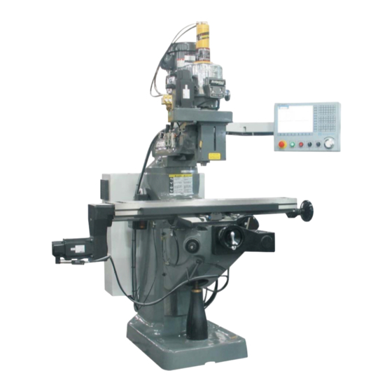
CHAPTER 1 - MACHINE SPECIFICATIONS BASIC COMPONENTS Control Unit Z Axis Ball Screw Housing (3 Axis Machines Only) Keypad Turret Electrical Control Box Table Spindle Quill X-Axis Handwheel Y-Axis Handwheel Knee Crank (Handle Removed) Knee Column Base TP6891 Figure 1.1 - 3 Axis Milling Machine M-477A... -
Page 12: Physical Specifications
PHYSICAL SPECIFICATIONS TRAVEL Table travel (X axis) 30 in. 762 mm Saddle travel (Y axis) 12 in. 305 mm Quill travel 5 in. 127 mm Quill travel w/3rd axis 4.5 in. 114 mm Knee travel* (Z axis) 16 in. 406 mm Ram travel 12 in. -
Page 13: Ballscrews
BALLSCREWS Diameter 1.25 in. 32 mm Pitch 0.200 in. 5.08 mm POSITIONING Auto (X,Y) 100 ipm 2540 mm/min. Manual (X,Y) 100 ipm 2540 mm/min. Feedrate range (X,Y) 0.1 - 100 ipm 2 - 2540 mm/min. Minimum increment 0.0001 in. 0.003 mm MACHINE AND CONTROL PERFORMANCE Positioning accuracy over saddle ±... -
Page 14: Principal Dimensions
PRINCIPAL DIMENSIONS 5 Inch Quill Travel TP5660A Figure 1.2 - Principal Dimensions TABLE TRAVEL 30.0 in. 762 mm TABLE LENGTH 48 in. 1219 mm Dimension Minimum 82 [2083] 51 [1295] 8.75 [222] 2.5 [64)] 6.75 [171] Maximum 84 [2140] 63 [1600] 20.75 [527] 18.25 [470] 12 [305]... -
Page 15: Machine Dimensions
MACHINE DIMENSIONS FRONT VIEW 67" 46½" (Back Splash) 48" (Optional Coolant Tank) 97" (Table at -X Travel Limit) TP5662A Figure 1.3 - Machine Dimensions (Front View) M-477A... -
Page 16: Side View
SIDE VIEW 84" with Power Draw Bar 82" without Power Draw Bar 13.0" Maximum 1.0" Minimum 47.4" Maximum 31.4" Minimum TP5661A Figure 1.4 - Machine Dimensions (Side View) M-477A... -
Page 17: Head Specifications
HEAD SPECIFICATIONS Power 2.0 HP Motor RPM 1800 RPM Speed Ranges - RPM Stepless 60 - 500 HIGH 500 - 4200 Quill Travel 5.0 in. 127 mm Quill Diameter 3.375 in. 86 mm Spindle Tapers #30 Q.C. Spindle Diameter 1.875 in. 48 mm Spindle Feed Rate 0.0015/Rev... -
Page 18: Head Dimensions
HEAD DIMENSIONS TP5663 Figure 1.5 - Head Dimensions M-477A... -
Page 19: Spindle Specifications
SPINDLE SPECIFICATIONS Spindle Taper Spindle speeds - RPM 60-4200 Motor *2 HP 1.5 kw Quill travel 5 in 127 mm Power feed of Quill 0.0015 in. 0.04 mm per rev of Spindle (3 rates) 0.003 in. 0.08 mm 0.006 in. 0.15 mm Collet capacity 1/8 - ¾... - Page 20 - NOTES - 1-10 M-477A...
-
Page 21: Chapter 2 - Installation
CHAPTER 2 - INSTALLATION UNCRATING Carefully remove crating and skids so that the machine and parts are not marred, scratched or impaired. In the event of damage in transit, communicate IMMEDIATELY with our representative and the transportation company making delivery. Retain the lag bolts used to secure the machine to the skid. -
Page 22: Machine Floor Plan
MACHINE FLOOR PLAN The machine floor plan, shown in Figure 2.2, can be used to determine floor space requirements. 34 [864] 35.25 [895] 22.75 [508] [578] [2159] Electrical Power Input 1-3/8 Diameter for 1" Conduit Fitting Coolant Reservoir [534] (Open for Inspection) 28.5 [724] 62 [1575] Removable Coolant Pan (Option) -
Page 23: Lifting The Machine
LIFTING THE MACHINE - WARNING - Observe all instructions given in Figure 2.3. Improper lifting could cause seri- ous injury or damage to the machine. Refer to Chapter 1 for the machine weight. Check the position of the ram and table before lifting with a sling. The machine should be lifted by placing a sling under the ram as shown in Figure 2.3. -
Page 24: Placing Machine On A Solid Foundation
PLACING MACHINE ON A SOLID FOUNDATION - WARNING - The machine should be placed on a solid level floor with shims or anti-vibra- tion pads to insure machine base is positioned evenly to prevent rocking. Refer to Figure 2.4. 1. When setting machine on a concrete foundation, use grout (thin mortar) to compensate for any unevenness in the concrete, as well as to provide a solid foundation at all contact points. - Page 25 - NOTE - It is recommended the machine be secured to the floor to prevent movement or tip- ping due to off-center loading. The lag bolts used to secure the machine to the skid during shipment can be used to secure the machine to the floor. 5.
-
Page 26: Control Pendant Installation
CONTROL PENDANT INSTALLATION - WARNING - Two people are required to perform the control pendant installation. 1. Check all contents for damage. 2. Remove lower mounting bracket "C", Figure 2.7, from the back of the control pendant. 3. Slide upper mounting bracket "D" over the end of rod "E". 4. - Page 27 8. Turn main disconnect switch handle “I”, Figure 2.9, to the OFF position. 9. Release two latches "J" and open the power case door. 10. Remove a hole plug from the bottom of the power case. 11. Feed the fiber optic cable in the wire carrier through cord grip "K", Figure 2.10, and into the power case.
-
Page 28: Power Case Inspection
POWER CASE INSPECTION 1. Check all electrical connections in the power case to be sure they are secure. 2. Check the spindle overload setting: A) Verify the spindle overload is properly set for the machine voltage. The table shown below reflects the data shown on the spindle Full Load Amp tag, located on the front of the machine head. -
Page 29: Connect The Electrical Power
CONNECT THE ELECTRICAL POWER - NOTE - Due to the variation of local electrical codes, Hardinge recommends the local utility supply company be consulted to determine exact service and wiring requirements. Maximum impedance of the protective ground connection must not exceed 1.0 Ohm. -
Page 30: Protective Ground
PROTECTIVE GROUND - DANGER - PROTECTIVE GROUND IS REQUIRED. It minimizes the exposure to personal shocks in the event of circuit shorts or other malfunctions. Failure to ensure protective ground may create electrical shock hazard, causing serious per- sonal injury or death. Protective Ground (Chassis or Safety Ground) establishes a low impedance path from the equipment enclosure and other mechanical parts of the system to earth ground. -
Page 31: Prestart Checks
PRESTART CHECKS Make a careful check of the following conditions before applying power. 1. The floor is of sufficient quality to support the machine and maintain machine level. 2. The incoming power is within +/- 10% of voltage specified on the machine data plate. 3. -
Page 32: Start-Up Checklist
START-UP CHECKLIST - NOTE - Refer to the programmer's and operator's manual (M-476) for information on pow- ering up the machine and homing the machine axes. 1. Power up the machine and home the machine axes. - CAUTION - DO NOT shift the HI-NEUTRAL-LO lever when the spindle is motion. 2. -
Page 33: Head Tram
HEAD TRAM The head tram was properly set at the factory, but it is recommended the head tram be checked to ensure that it has not moved during shipment. Specification: ±.0005" in 9 inches 1. Install an indicator in the spindle 2. -
Page 34: Axis Tram Adjustment
X Axis Tram Adjustment 1. Loosen four locknuts "R", Figure 2.20, but leave some drag for fine adjustment. 2. Sweep the indicator around the spindle centerline as shown in Figures 2.16 and 2.17. 3. Compare the indicator run-out with the specification on page 2-13. -
Page 35: Y Axis Tram Adjustment
Y Axis Tram Adjustment 1. Loose three ram locking bolts "T", Figure 2.23. 2. Sweep the indicator around the spindle centerline as shown in Figures 2.18 and 2.19 3. Compare the indicator run-out with the specification on page 2-13. 4. Use vertical adjustment worm shaft "U", Figure 2.23, to adjust the Y axis tram as needed. 5. - Page 36 - NOTES - 2-16 M-477A...
-
Page 37: Chapter 3 - Preventive Maintenance
CHAPTER 3 - PREVENTIVE MAINTENANCE PREVENTIVE MAINTENANCE SCHEDULE The following maintenance schedule is approximate and components may need attention more frequently if excessive environmental pollution is present. Preventive maintenance frequency is for single shifts and should be increased proportionally when work is for two or three shifts per day. Refer also to "Dry Cutting", page 3-2, for additional considerations. -
Page 38: Dry Cutting
DRY CUTTING A additional consideration for preventive maintenance is dry cutting. In this case, the machine is used to cut materials such as cast iron, magnesium or carbon that produce unusually large amounts of dust in the air. This is considered to be a Hostile environment which requires more than the average amount of care. -
Page 39: Maintenance Procedures
MAINTENANCE PROCEDURES DAILY Check the Automatic Lubrication System Oil Level The most convenient course of action is to keep the level of oil to the top of the tank. Check the oil level daily. If the reservoir is allowed to empty, a liquid level switch at its base will not allow the spindle to start. -
Page 40: Apply Oil To The Drawbar
Apply Oil to the Drawbar ® ® Move the quill downward approximately 2 inches and apply five drops of Mobil Vactra Oil No. 4 to the top of the drawbar. Refer to the lubrication plate on the right side of the machine head. Apply Oil to the Spindle Add five drops of Mobil DTE Light oil to spindle oil cup "B", Figure 3.1. -
Page 41: Monthly
MONTHLY Clean the Machine Exterior, Clear Air Intakes, and Exhausts Clear dirt and chips from machine at the end of the day Use an industrial wet or dry vac- uum cleaner; then, wipe carefully to remove damage-causing abrasive material. Do not use compressed air to clean the machine. -
Page 42: Semi-Annually
SEMI-ANNUALLY Check the Pneumatic Regulator System Bowl Check the pneumatic regulator system bowl. Fill the lubricator bowl if necessary. ® When the level drops below the EMPTY line, fill to FULL with Mobil DTE Light oil. 1. Shut OFF the air pressure. 2. -
Page 43: Check The Spindle Drive Belt For Dirt And Wear
Check the Spindle Drive Belt for Dirt and Wear If the housing itself is excessively dirty, the belt may be worn or weak. 1. Remove the spindle drive belt cover. 2. Inspect the belt for wear, cracks, or damage. 3. If the belt looks worn, call Dealer Service to replace it. 4. - Page 44 - NOTES - M-477A...
-
Page 45: Chapter 4 - Maintenance
CHAPTER 4 - MAINTENANCE SPINDLE DRIVE MOTOR REMOVAL 1. Run head to adjust to lowest speed. 2. Disconnect power. 3. Remove three screws “A” and cover “B”, Figure 4.1. 4. Use two of three screws “A” to compress spring “C”. 5. -
Page 46: Drive Belt Replacement
DRIVE BELT REPLACEMENT 1. Remove the spindle drive motor as described on page 4-1. 2. Remove three screws “F”, Figure 4.3. Insert them into the adjacent tapped holes and withdraw bearing housing “G”. 3. Remove the two screws and bushings “H”. 4. -
Page 47: Timing Belt Replacement
TIMING BELT REPLACEMENT 1. Remove the motor. 2. Lower the quill to full extent. 3. Remove two lower cap screws “M”, Figure 4.4, from the speed changer housing. 4. Remove four cap screws “N”. 5. Remove top assembly “O” and tap to clear dowels. 6. -
Page 48: Brake Shoe Replacement
BRAKE SHOE REPLACEMENT 1. Remove the top housing. Refer to: • Spindle Drive Motor Removal, on page 4-1 • Timing Belt Replacement, on page 4-3 2. Remove two screws “P”, Figure 4.5. 3. Remove clutch hub assembly “Q”. 4. Replace brake shoes “R”. 5. -
Page 49: Micro Feed Trip Assembly And Quill Removal
MICRO FEED TRIP ASSEMBLY AND QUILL REMOVAL 1. Remove screw “A”, Figure 4.6. 2. Remove ball reverse lever “B”: A) Thread a #4-40 screw into the ball reverse lever. B) Use the #4-40 screw to remove the ball reverse lever. 3. -
Page 50: Balance Spring Replacement
BALANCE SPRING REPLACEMENT 1. With the quill at the maximum UP position, apply the quill lock. 2. Remove screw “I”, hub “J”, and key “K”, Figure 4.7. 3. Remove screws “L”, allowing the housing to rotate slowly, releasing spring tension. 4. -
Page 51: Feed Trip Adjustment
FEED TRIP ADJUSTMENT 1. Release locknut “N”, Figure 4.8. 2. Engage trip handle “P”. 3. Adjust the micro nuts against quill stop “O”. - NOTE - The machine will not be able to drill if adjusting screw “Q” is set too light. 4. -
Page 52: Collet Aligning Screw Replacement
COLLET ALIGNING SCREW REPLACEMENT - CAUTION - DO NOT attempt to remove nose cap before removing set screw “R”. Doing so will cause serious dam- age. 1. Use a felt pen to mark a reference line on the quill and nose cap “S”, Figure 4.9. 2. - Page 53 TABLE GIB ADJUSTMENT The table gib is used for adjusting the table bearing on the saddle. The gib serves as a guide for the table travel. 1. Clean the front angular face of the saddle. - NOTE - Figure 4.10 shows how the left side in- dicator is mounted.
- Page 54 5. Pull the right end of the table by applying 50 lb [222 N] and push the left end of the table by applying 50 lb [222 N]. 6. Record both indicator readings. Ignore + or - signs. Refer to Table 4.1 for the optimum indicator readings. Indicator Readings Values, Inch [Millimeter] Minimum Indicator Readings...
-
Page 55: Saddle Gib Adjustment
SADDLE GIB ADJUSTMENT The saddle gib is used for adjusting the saddle bearing on the knee. The gib serves as a guide for the saddle travel. - NOTE - Observe the orientation of the front saddle wiper before removing. 1. Remove three screws and slide front saddle wiper "B", Figure 4.13, off the machine. 2. - Page 56 Rear Indicator Direction of Force Applied to the Table Table Saddle Front Indicator TP6999 Figure 4.15 - Indicator Positions for Saddle Gib Adjustment 9. If the readings do not exceed .0004 inches [.010 mm], gib adjustment is not required. If the readings exceed .0004 inches [.010 mm]: A) Adjust the gib by tightening gib screw "C", Figure 4.16, slightly until a slight drag is felt...
-
Page 57: Knee Gib Adjustment
KNEE GIB ADJUSTMENT 1. Move the X axis to position the table at the approximate midpoint of travel. 2. Move the Y axis to position rear saddle surface "D", Figure 4.17, approximately four inches [100 millimeters] from column dovetail surface "E", Figure 4.18. 3. - Page 58 - NOTES - 4-14 M-477A...
-
Page 59: Chapter 5 - Automatic Lubrication System
CHAPTER 5 - AUTOMATIC LUBRICATION SYSTEM INTRODUCTION The first section of this chapter supplies general information concerning the machine automatic lubrication system. The following pages provide adjustment procedures and parts replacement information. OVERVIEW The bearings in the spindle, the spindle drive transmission, and the ballscrew mountings have antifriction angular contact bearings greased for life. -
Page 60: Lubricator Unit
LUBRICATOR UNIT MAINTENANCE 1. Check the oil level daily and refill the reservoir when required. 2. Check the system periodically for loose or broken tubing, worn hoses, and loose fittings and connections. 3. Check the bearing surfaces daily. If there is too little oil, check the following and repair as necessary: •... -
Page 61: Operation
OPERATION Lubricator Pump - NOTE - The lubricator can also be actuated manually by raising and releasing the Manual Feed knob. The lubricator is a motor-driven piston pump, spring-discharge type. Pump cycle time is controlled by an integral gear reduction in the motor. Adjusting the Oil Discharge Volume Per Cycle The stem on the Manual Feed knob has numbered graduations, ranging from 1 to 5. -
Page 62: Lubricator Filter
LUBRICATOR FILTER - NOTE - The lubricator filter should be replaced a minimum of once a year. The lubricator filter is rated at 40 micron particle separation. It should be inspected periodically and replaced as required. Remove the filter as follows: Slide the spring clip OFF. -
Page 63: Lubrication Oil Specification
LUBRICATION OIL SPECIFICATION GENERAL DESCRIPTION The way lubrication must contain tackiness additives. The way lubrication must not contain lead or chlorine compound additives USES Machine tool way, heavy loaded journals, and screws. SPECIFICATION TABLE Lubricant specifications listed below are minimum standards which must be met by all lubricants recommended for use on the machine. - Page 64 - NOTES - M-477A...
-
Page 65: Chapter 6 - Safety Guard Installation
CHAPTER 6 - SAFETY GUARD INSTALLATION INTRODUCTION - NOTE - American National Standard B11.8 and O.S.H.A. Section 1910.212 assign respon- sibility for point of operation safeguarding of milling machines to the employer/user. Point of operation safeguarding should be used on milling machines to the greatest extent possible to prevent injury resulting from the cutter, chips, or coolant. -
Page 66: Installation Procedures
INSTALLATION PROCEDURES MACHINES WITH R-8 SPINDLE The manufacturer has drilled and tapped two holes in the nose cap of the spindle to be used for mounting the guard (the two untapped holes serve to remove the nose cap with a spanner wrench). 1. -
Page 67: Machines With Erickson #30 Or Universal #200 Quick-Change Spindle
MACHINES WITH ERICKSON #30 OR UNIVERSAL #200 QUICK-CHANGE SPINDLE If the machine has either an Erickson #30 or a Universal #200 quick-change spindle, the manufacturer has drilled and tapped four #8-32 holes in the nose cap of the spindle for mounting the guard. -
Page 68: Component Lists
COMPONENT LISTS R-8 SAFETY GUARD ASSEMBLY (Part Number BP 11191200) Refer to Figure 6.1 for component identification. Item Part Number Description Quantity BP 11011031 Screw, Socket Hd Cap, .250”-20 x .625” BP 12191201 Ring, Guard BP 11191204 Shield, Left Side BP 11191206 Shield Assy, Top BP 11665810... -
Page 69: Quick-Change Safety Guard Assembly
QUICK-CHANGE SAFETY GUARD ASSEMBLY (Part Number BP 11190341) Refer to Figures 6.1 and 6.2 for component identification. Item Part Number Description Quantity BP 11011031 Screw, Socket Hd Cap, .250”-20 x .625” BP 11191204 Shield, Left Side BP 11665810 Screw, Button Hd Cap, #10-32x.750” BP 11010065 Washer, Plastic, #10-32 BP 11010055... - Page 70 - NOTES - M-477A...
-
Page 71: Chapter 7 - Parts Listings
CHAPTER 7 - PARTS LISTINGS HEAD TOP HOUSING TP5340 M-477A... - Page 72 HEAD TOP HOUSING ITEM PART NUMBER DESCRIPTION BP 11011033 Screw, Socket Hd Cap, ¼”-20 x ¾” Lg BP 12180094 Cap, Top Bearing BP 11181977 Washer, Wave Spring BP 11180252 Bearing, Ball, Fafnir #9107 NNP BP 11180848 Ring, Snap, #5100-137 BP 11011069 Screw, Socket Hd Cap, 5/16”-18 x 6”...
- Page 73 ITEM PART NUMBER DESCRIPTION BP 11011287 Screw, Stainless Steel, ¼”-20 x ¼” BP 11182126 Insert, Plastic Replaceable Type BP 12550046 Assembly, Adjustable Motor Varidisc BP 11182083 Spring, Varidisc Motor Shaft BP 11550003 Collar, Adjustable Varidisc Spring BP 11011022 Screw, Socket Hd Cap, #10-24 x 1.00” Lg BP 11150843 Ring, Snap BP 11011052...
-
Page 74: Head Back Gear
HEAD BACK GEAR TP5341 M-477A... - Page 75 HEAD BACK GEAR ITEM PART NUMBER DESCRIPTION BP 11011710 Nut, Hex, 5/16" BP 11180133 Dial, Spindle Speed BP 11183646 Bushing, Bronze, Boston #B810-4 BP 11011380 Screw, Full Dog Socket Hd Set, ¼”-20 x ½” Set BP 12180055 Housing, Speed Changer BP 12182003 Block, Plastic Bearing BP 11011031...
- Page 76 ITEM PART NUMBER DESCRIPTION BP 12180063 Spacer, Bull Gear Bearing BP 12180052 Housing, Gear BP 11181650 Bolt, Tee BP 11181906 Washer, Flat, 15/32" ID x 15/16" OD x 1/16" BP 11011750 Nut, HDN Finished Hex Jam, 7/16”-14 BP 11181986 Washer, Ball Bearing Gear Sleeve BP 12180054 Bracket, Fixed Clutch Bracket BP 11011246...
- Page 77 ITEM PART NUMBER DESCRIPTION BP 12180076 Cap, Bull Gear Pinion Bearing BP 11011011 Screw, Socket Hd Cap, #10-24 x 5/8" Lg BP 12550016 Pulley, Timing Belt BP 11191738 Nut, Hex Jam, 5/8-18" BP 11182912 Nameplate, Speed Change BP 11011139 Screw, Flat Hd Machine, #8-32 x 0.750" BP 11182897 Plate, Lubrication BP 11182655...
-
Page 78: Head Lower Housing
HEAD LOWER HOUSING TP5343 M-477A... - Page 79 HEAD LOWER HOUSING ITEM PART NUMBER DESCRIPTION BP 11011445 Screw, Round Hd Cap, #10-24 x 3/8" Lg BP 12190163 Washer, Bevel Pinion BP 12190203 Gear, Feed Bevel Pinion BP 12190164 Sleeve, Feed Worm Gear Shaft BP 11192303 Bushing, Worm Cradle BP 11011287 Set Screw, ¼”-20 x 5/16"...
- Page 80 ITEM PART NUMBER DESCRIPTION BP 12190146 Gear, Feed Driving BP 12190176 Key, Round End, 1/8" Sq. x ¾" BP 12190145 Shaft, Cluster Gear Input BP 12190144 Gear, Feed Drive BP 1110-310 Bearing, Torrington Needle, B-66 BP 11193637 Bushing BP 28007307 Gear, Worm Speed Control BP 12190155 Bushing, Feed Worm Shaft...
- Page 81 ITEM PART NUMBER DESCRIPTION BP 11192032 Spring, Compression, ¼" Dia. x 1-1/4" BP 12190096 Brass, Overload Clutch Lever Spring Plunger BP 12190106 Bushing, Quill Pinion Shaft BP 12190104 Spacer, Pinion Shaft Worm Gear BP 11190103 Gear, Overload Clutch Worm BP 28007059 Ring, Overload Clutch BP 11190870 Ring, External Retaining...
- Page 82 ITEM PART NUMBER DESCRIPTION BP 11190238 Bearing, Spindle BP 12193513 Spacer, Bearing BP 11011265 Setscrew, 1/4”-UNC x ¼" BP 12193540 Screw, Collet Alignment, ¼-32" BP 11011545 Setscrew, Special Locking, ¼”-32 x 1/8" 142# BP 12190192 Quill BP 28300336 Nut, Steel, #6-32 NC BP 28300609 Setscrew, #6-32 x ¾"...
- Page 83 ITEM PART NUMBER DESCRIPTION BP 28007150 Pin, Outside Clock Spring BP 28007064 Pinion, Quill BP 12190085 Lever, Reverse Trip Ball BP 12190086 Plunger, Feed Reverse Trip BP 12190087 Screw, Reverse Trip Ball Lever BP 11192207 Gear, Worm BP 11013077 Key, Woodruff #5 BP 11011370 Setscrew, Socket Hd, 1/4”-UNC x 20 x 3/8"...
-
Page 84: Basic Machine
BASIC MACHINE TP5344 7-14 M-477A... - Page 85 BASIC MACHINE ITEM PART NUMBER DESCRIPTION BP 12190178 Housing, Adjustable Gear Tilting Quill BP 12069013 Assembly, Ram Adapter BP 11060603 Scale, Adapter BP 11060892 Ring, External Retaining BP 11062206 Worm, Vertical Adjusting BP 12060130 Shaft, Vertical Adjusting Worm BP 12060138 Key, Sq., 0.188”...
- Page 86 ITEM PART NUMBER DESCRIPTION BP 12060487 Saddle, with Chrome BP 12060093 Holder, Left Hand Column Wiper BP 12060146 Gib, Knee/Column BP 11011031 Screw, Socket Hd Cap, 0.250”-20 x 0.625" BP 12060094 Holder, Right Hand Column Wiper BP 11062405 Guard, Upper Chip, Kn 60 11060153 BP 11060152 Guard, Lower Chip BP 11060493...
- Page 87 ITEM PART NUMBER DESCRIPTION BP 12060209 Column BP 11011074 Screw, Socket Hd Cap, 3/8”-16 x 1" BP 12060207 Pedestal BP 12060051 Nut, Elevating Screw BP 11011195 Screw, Socket Hd Cap, ¼”-20 x 1" BP 12650180 Block, Stop (Head Rotation) BP 11152094 Plunger, Spring BP 11011017 Screw, Socket Hd Cap, #10-32 x 0.500"...
-
Page 88: Left End Of X Axis Ballscrew
LEFT END OF X AXIS BALLSCREW TP5726 Torque to Torque screws evenly 9 lb-ft to 30 lb-in [3.4 Nm] [12.2 Nm] Torque to 50 lb-ft [67.8 Nm] Motor Torque screws evenly to 30 lb-in [3.4 Nm] Force of 4lb at 0.098 deflection 7-18 M-477A... - Page 89 LEFT END OF X AXIS BALLSCREW ITEM PART NUMBER DESCRIPTION BP 11010210 Screw, Socket Hd Cap, #8-32 x 1.000" BP 61705552 Washer, Plastic Nylite, 4 mm BP 24649915 Pulley Assembly (40-T) BP 11011030 Screw, Socket Hd Cap, ¼”-20 x 0.500" BP 12749003 Bracket BP 11011075...
-
Page 90: Right End Of X Axis Ballscrew
TP5727 RIGHT END OF X AXIS BALLSCREW ITEM PART NUMBER DESCRIPTION BP 12060347 Table, 48" BP 1260115 Bracket BP 11011074 Screw, Socket Hd Cap, 3/8”-16 x 1.000" BP 11060204 Bearing, Fafnir H 204K BP 12060214 Dial BP 12060078 Locknut BP 11011755 Nut, Jam, ½”-20 NF BP 12150164 Washer, Flat... -
Page 91: Ballscrew With Nut Block
Torque to 35 lb-ft [47.5 Nm] TP5728 BALLSCREW WITH NUT BLOCK ITEM PART NUMBER DESCRIPTION BP 12060347 Table, 48" BP 12060487 Saddle BP 11011074 Screw, Socket Hd Cap, 3/8”-16 x 1" BP 12749023 Nutblock BP 11746208 Ballscrew BP 11011074 Screw, Socket Hd Cap, 3/8”-16 x 1.000" M-477A 7-21... -
Page 92: Y Axis Drive With Nutblock
Y AXIS DRIVE WITH NUTBLOCK Force of 4lb at 0.162 deflection Motor Extended Drive Force of 4lb at 0.187 deflection Compact Drive Torque to Torque evenly to 50 lb-ft 9 lb-ft [12.2 Nm] [67.8 Nm] TP5729 7-22 M-477A... - Page 93 Y AXIS DRIVE WITH NUTBLOCK ITEM PART NUMBER DESCRIPTION BP 1101073 Screw, Flat Hd Cap, 5/16”-24 x 0.620" BP 12746205 Housing (Compact Drive) BP 12746117 Housing (Extended Drive) BP 12746214 Cover (Compact Drive) BP 12746118 Cover (Extended Drive) BP 64649912 Assembly, Assembly (20-T) BP 11980227 Screw, Socket Hd Cap, #8-32 x 1.250"...
-
Page 94: 3Rd Axis Option
3RD AXIS OPTION TP6973 7-24 M-477A... - Page 95 3RD AXIS OPTION ITEM PART NUMBER DESCRIPTION QUANTITY BP 11749351 Motor Mount Plate Assembly BP 11749352 Scale Cable Tube BP 11749354 Left Mount Plate Assembly BP 11749355 Top Cover Assembly BP 11749325 Pulley, Motor Bp 11749326 Pulley, Ballscrew BP 11749420S8 Belt BP 11749356 1/8"...
-
Page 96: Operator Pendant
OPERATOR PENDANT (DC150 Motion Control System) TI5563 7-26 M-477A... -
Page 97: Power Case, External View
POWER CASE, EXTERNAL VIEW (DC150 Motion Control System) TI5564 M-477A 7-27... -
Page 98: Power Case, Internal View
POWER CASE, INTERNAL VIEW (DC150 Motion Control System) TI5565A 7-28 M-477A Revised: March 28, 2008... -
Page 99: Power Case Terminal Strips
POWER CASE TERMINAL STRIPS (DC150 Motion Control System) TI5566A M-477A 7-29 Revised: March 28, 2008... -
Page 100: Operator Pendant And Power Case Component List
OPERATOR PENDANT AND POWER CASE COMPONENT LIST (DC150 Motion Control System) ITEM PART NUMBER DESCRIPTION BP 0004158SZ Enclosure Control Electrical BP 0001990SZ02 Panel, Rear BP 0004158F BP 0004158FG Guard, Fan BP 0004158FC Cable, Fan BP 0004158FFLT Filter, Fan BP 0010016DS Switch, Disconnect BP 0010016DH Handle, Disconnect... - Page 101 BP 00005490110 Cord Grip, 3/4", 6.5-14MM BP 11597846 Cable, Home Switch Z Axis BP 00005490109 Z Axis Resolver Cable BP 00005490108 Z Axis Motor Cable BP 00005490169 Cable, DC150 to Z Axis BP 00005490174 24VDC Z Axis Power Power Cable BP 0003277MRS Sub-Assembly, Mr Snubber BP 11598898...
- Page 102 BP 00005490065 3/4" Conduit Fittng BP 00005490066 3/4" Conduit BP 00005490094 Cable with Bulkhead Connector BP 00005490095 Cable with Phone Jack BP 00005490096 Cable with Jumper BP 00005490097 RJ 45 Ethernet Jumper BP 00005490098 RJ45 CAT5 2-PR-2’ BP 00005490099 USB Extension Cable BP 00005490100 USB Extension Cable BP 00005490101...
- Page 103 - NOTES - M-477A 7-33...
Need help?
Do you have a question about the Bridgeport EZ Vision and is the answer not in the manual?
Questions and answers