
Related Manuals for Hardinge SERIES I

Summary of Contents for Hardinge SERIES I
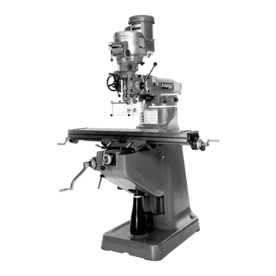
- Page 1 INSTALLATION, OPERATION, MAINTENANCE, AND PARTS LIST SERIES I MILLING MACHINES TP5260 Revised: August 29, 2005 Manual No. M-450 Litho in U.S.A. Part No. M -0009500-0450 June, 2003...
-
Page 2: Chapter 2 - Operation
CHAPTER 2 - OPERATION HEAD CONTROLS TP5285 Figure 2.1 - Head Controls Parts Assembly M-450... -
Page 3: High-Low Range Switch
HIGH-LOW RANGE SWITCH High-Low Range Switch “A”, Figure 2.2, is a motor reversing switch. When the attachment is in direct drive (HIGH SPEED), the motor and spindle are turning in a clockwise direction as viewed from the top of machine. When the attachment is in “Back Gear”... -
Page 4: Spindle Brake
SPINDLE BRAKE Spindle Brake “C”, Figure 2.4, can be moved in either direction to stop spindle; however, when locking spindle, brake lever should be moved either by pulling towards the operator or pushing away from the operator, then raised. When brake is worn out it has to be replaced. -
Page 5: Quill Stop Knob
QUILL STOP KNOB Quill Stop Knob “E”, Figure 2.6, is used to disengage automatic feed in either direction as well as the stop point setting working depths. MICROMETER NUT Micrometer Nut “F”, Figure 2.6, is used for setting depths. Each graduation on nut indicates .001” of depth, it reads directly to scale mounted along the side of it. -
Page 6: Feed Control Lever
FEED CONTROL LEVER Feed Control Lever “I”, Figure 2.8, engages overload clutch on pinion shaft when positioned left and will stay engaged until either quill stop comes in contact with micrometer adjusting nut, forcing feed control lever to drop out automatically, or release manually by engaging lever to right. -
Page 7: Quill Feed Handle
QUILL FEED HANDLE Quill Feed Handle “M”, Figure 2.10, is used to raise and lower the quill manually. It is generally recommended that handle be engaged when using the power feed. It may be removed by simply pulling handle off. TP5294 Figure 2.10 - Quill Feed Handle POWER FEED TRANSMISSION ENGAGEMENT... -
Page 8: Hi-Neutral-Lo Lever
HI-NEUTRAL-LO LEVER The Hi-Neutral-Lo Lever “O”, Figure 2.13, is used to put the attachment into either back gear or direct drive. Rotate the spindle by hand to facilitate meshing of clutch or gears. Neutral is provided to permit free spindle rotation for indicating and setup work. In the high speed position (direct drive) the spindle is driven by tapered clutch teeth. -
Page 9: Speed Change Handwheel
SPEED CHANGE HANDWHEEL - CAUTION - DO NOT attempt to change spindle RPM unless the motor is running. Dial speeds will only be approximate. Belt wear will cause a slight variation in speeds from what is indicated on the dial. Spindle speeds are adjusted by turning Speed Change Handwheel “P”, Figure 2.14, on the front of the belt housing. - Page 10 MOTOR Motor “Q”, Figure 2.15, has the following specifications: • 2 HP variable speed (with 2J head) • 3 HP 30 minute duty rate DRAWBAR When tightening or loosening the Drawbar “R”, Figure 2.15, it is necessary to lock the spindle. To accomplish this, use the spindle brake which is located on the left side of the belt housing, pulling towards the operator or pushing away from the operator until it binds, then raise the quill feed handle.
-
Page 11: Operational Procedures
OPERATIONAL PROCEDURES Spindle Speed - CAUTION - DO NOT change speed when spin- dle is stationary. Change speed only when spindle is running. To change speed within range: 1. Start spindle. 2. Turn handwheel “A”, Figure 2.16, to select required speed. TP5300 Figure 2.16 - Spindle Speed Change Back Gear (Low Speed) - Page 12 Direct Drive (High Speed) To change range from back gear to direct drive: 1. Switch “B” to OFF (Stop spindle rotation). 2. Move lever “C”, Figure 2.18, through neutral to HIGH. High 3. Rotate spindle by hand until the clutches are felt to engage.
-
Page 13: Automatic Feed
AUTOMATIC FEED - NOTE - Maximum loading .375” (9.5mm) diameter drill steel. 1. Ensure quill lock “G”, is off. 2. Set micrometer dial “H” to required depth. 3. Engage auto quill feed “D” when motor has stopped 4. Select feed rate “I”. 5. - Page 14 HEAD OPERATIONAL PROCEDURES Spindle Brake Brake lever has capability to rotate in either Brake direction to brake and lock. 1. CAM upwards to lock and prevent movement of spindle (see Figure 2.21). Brake Turn and Lift to Lock TP5306 Figure 2.21 - Spindle Brake Quill Sensitive Hand Feed 1.
- Page 15 ’J’ causing fluctuation of the quill feed which can be felt through the sensitive feed handle. It is advised to call Hardinge service department before attempting this procedure. 1. Loosen three locknuts “J”, Figure 2.23.
- Page 16 Move Ram Slide 1. Use wrench provided with machine to loosen bolts “L” and “M”, Figure 2.25. 2. Use wrench to move the slide to the desired position using bolt “N”. Rear 3. Tighten bolts “L” and “M”, starting with the rear bolt.
- Page 17 Table Clamping The table clamp levers are located on front of saddle and should always be clamped when longitudinal movement is not required (see Figure 2.28). Lock Unlock Table Clamp Levers TP5311 Figure 2.28 - Table Clamping Knee Clamping The knee clamping levers are at the left side of the knee and front of knee. Leave clamped at all times unless using knee in operation (see Figure 2.27).
-
Page 18: Power Feed Controls
POWER FEED CONTROLS OPERATIONAL PROCEDURES Variable Table Feeds Power Feed (X-Axis) Table Feed Engage Lever Feed Left Neutral Feed Right TP5313 Figure 2.29 - Variable Table Feeds Quick-Release Safety Handle Grip handle and turn to either left or right until spring loaded plunger engages in position. - NOTE - Ball crank handle is a safety device. -
Page 19: E-Head Controls
E-HEAD CONTROLS OPERATIONAL PROCEDURES Head Swivel 1. Loosen the four locknuts (see Figure 2.32). Support unit to prevent free fall. 2. Swivel to required angular setting. 3. Tighten the four locknuts first to 25 lb-ft. Then 50 lb-ft (ref. Page 1-4). - NOTE - Remove the screw sealing vent hole before operating machine (ref. - Page 20 To Change Speed 1. Disconnect power from head. 2. Loosen the two motor locknuts (see Figure 2.33). 3. Slide motor forward. 4. Position vee belt on appropriate pulleys. 5. Slide motor to rear to tension vee belt. 6. Tighten the two motor locknuts. With 50 cycle 1425 rpm 60, 85, 120, 170, 245 350 strokes per minute.
- Page 21 Clapper Box To Swivel Clapper Box: 1. Loosen the two set screws “O”, Figure 2.35. 2. Rotate to the required angular setting. 3. Tighten the two set screws “O”. Tool Relief 1. Loosen set screw “P”. Rear View The tool will now have automatic relief on the return stroke.
- Page 22 - NOTES - M-450 2-21...
Need help?
Do you have a question about the SERIES I and is the answer not in the manual?
Questions and answers