Advertisement
Table of Contents
VON DUPRIN
Installation Instructions
6000 Series Electric Strike DS Replacement Kit
Double Switch
Type A, Type A Gold
Type B, or Type B Gold
1
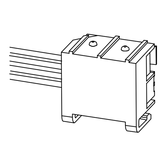
Remove strike from door frame, unplug
wiring plugs, and remove strike box from
faceplate as shown (Figure 1).
DS plug
Strike box
Solenoid
plug
Figure 1
931229_00(0) Copyright © 2001 Ingersoll-Rand Company. All rights reserved.
®
PARTS LIST
INSTALLATION
!
Turn off power to strike before removal.
l
Strike mounting screws
Faceplate
Configuration of
faceplate and
strike box may vary
from illustration
Strain relief
NOTES
2
Remove box cover (5/64” Allen wrench)
and remove old double switch (Figure 2).
Button head
screws (2)
Button head screw
#6-32 X 1/4” (2)
Strike box
cover
Old double
switch
Figure 2
Advertisement
Table of Contents

Subscribe to Our Youtube Channel
Related Manuals for Ingersoll-Rand Von Duprin 6000 Series


Summary of Contents for Ingersoll-Rand Von Duprin 6000 Series
- Page 1 Strike box screws (2) Strike mounting screws cover Faceplate DS plug Strike box Solenoid plug Configuration of faceplate and strike box may vary Old double from illustration switch Figure 1 Figure 2 931229_00(0) Copyright © 2001 Ingersoll-Rand Company. All rights reserved.
- Page 2 With keeper in closed position, install Snap new strain relief around DS wires new double switch (Figure 3). (Figure 4-1) and slide into box slot with flat part facing out as shown (Figure 4-2). Hold keeper in closed position while installing switch and after switch is installed or switch actuator can be damaged Keeper (in closed position)
Need help?
Do you have a question about the Von Duprin 6000 Series and is the answer not in the manual?
Questions and answers