Table of Contents
Advertisement
AND MAINTENANCE INSTRUCTIONS
This manual contains important service and maintenance information.
Make this manual available to all persons responsible for the service
and maintenance of these products.
Always operate, inspect and maintain this winch in accordance with American National
Standards Institute Safety Code (ASME B30.16) and any other applicable safety codes and
regulations.
Refer all communications to the nearest Ingersoll-Rand Material Handling Office or
Distributor.
Form MHD56111
Edition 2
March 1997
71296438
© 1997 Ingersoll-Rand Company
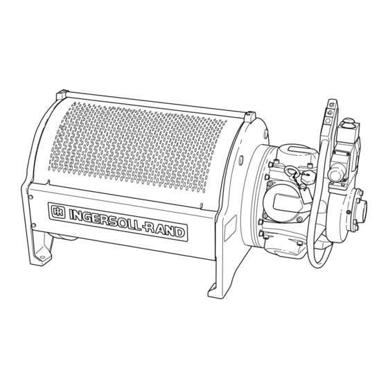
MODEL FA5A AIR WINCH
SUPPLEMENTAL SERVICE
Form MHD56111
Advertisement
Table of Contents
Troubleshooting

Related Manuals for Ingersoll-Rand FA5A


Summary of Contents for Ingersoll-Rand FA5A
- Page 1 Always operate, inspect and maintain this winch in accordance with American National Standards Institute Safety Code (ASME B30.16) and any other applicable safety codes and regulations. Refer all communications to the nearest Ingersoll-Rand Material Handling Office or Distributor. Form MHD56111...
- Page 2 FA5A Manual for all other information. The information is primarily intended for service and repair personnel who may be involved with the maintenance of FA5A Winches. It is recommended that the FA5A Winch Parts, Operation and Maintenance Manual MHD56087 be read prior to performing any service or repair work.
- Page 3 DISC BRAKE - GENERAL INFORMATION Description Components The disc brake for the FA5A winch bolts to the end of the The disc brake is comprised of two main sections. The first is winch opposite the motor. It has a cylindrical housing the housing and end cover plate.
- Page 4 DISC BRAKE TROUBLESHOOTING This section provides basic troubleshooting information. Specific causes to problems are best identified by thorough inspections performed by personnel instructed in safety, operation and maintenance of this equipment. The chart below provides a brief guide to common disc brake symptoms, probable causes and remedies. Symptom Cause Remedy...
-
Page 5: Section 1. Disc Brake Assembly
DISC BRAKE MAINTENANCE Read these instructions completely before working on the disc brake. Before working on the disc Before working on the disc WARNING brake, shut off the air to the brake, lift the vent on top of winch and remove the wire the disc brake housing to rope from the winch drum. -
Page 6: Cover
Lift the housing and end cover assembly off the support plate (22), and collect the three dowel pins (8). Separate the housing (7) from the end cover (4) and the diaphragm assembly. Remove and set aside the diaphragm (10), ring (5), and the diaphragm plate (6). -
Page 7: Spacer
The steel separator plates (14) must be flat, and not scored or discolored. They should measure 1.5 mm ±0.12 mm (0.060 ±0.005 inches). The three notches (on the outside of the separator plates) that engage the pins should not show any deformation. -
Page 8: Dowel Pin
Clutch Retainer Ring Install the retainer ring (25) that holds the inner race in position. Bearing Retainer Ring Inner Race (Dwg. MHP0845) Pressure Plate Position the support plate with the spring pockets facing up. Place the springs (21) into the pockets, and rest the pressure plate (12) on top of the springs with the stepped side of the pressure plate facing away from the springs. -
Page 9: Brake Shaft
17. Reinstall the air fitting and air line, and refill the disc brake with oil until the oil runs out of the oil level plug hole. Refer to “LUBRICATION” section in the FA5A Winch Parts, air line connection Oil Drain Plug Operation and Maintenance Manual MHD56087 for suitable oils. - Page 10 DISC BRAKE PARTS DRAWING One-Way Clutch Detail (Dwg. MHP0667) (Dwg. MHP0630)
-
Page 11: Table Of Contents
DISC BRAKE PARTS LIST ITEM DESCRIPTION TOTAL PART NO. OF PART QTY. - - - Disc Brake Assembly* 24140 Plug 71069009 Capscrew 71264717 Vent (25 psi) 71271175 Cover 23605 Ring 22028 Diaphragm Plate 22027 Housing 22026 Dowel Pin 71126882 Diaphragm 22031 One-way Clutch 71044853... -
Page 12: Section 2. Manual Band Brake Assembly
MANUAL BAND BRAKE ASSEMBLY - GENERAL INFORMATION Description The optional manual band brake for the FA5A winch is located on the end of the winch drum next to the air motor. It consists of a friction material lined steel band (the brake band) that encircles and grips a brake surface on the winch drum, and a manually operated engagement and release mechanism. -
Page 13: Capscrew
MANUAL BAND BRAKE TROUBLESHOOTING This section provides basic troubleshooting information. Specific Before troubleshooting the WARNING band brake, remove the wire rope causes to problems are best identified by thorough inspections performed by personnel instructed in safety, operation and from the winch drum. Failure to remove the wire rope maintenance of this equipment. - Page 14 MANUAL BAND BRAKE MAINTENANCE Read these instructions completely before working on the manual band brake. Before working on the band Service is most easily done with WARNING NOTICE brake, make sure the wire the motor end of the winch rope is slack. Releasing the blocked up approximately 10 cm [4 band brake while there is a load on the winch can inches].
- Page 15 Gently spread the ends of the brake band apart and slide it off the brake drum and onto the winch drum. Move the Brake Band onto the Winch Drum barrel diameter. (Dwg. MHP1033) Remove the Brake Band Gently spread the ends of the brake band apart far enough to from the Winch Drum barrel clear the winch drum barrel diameter and take it off the drum.
- Page 16 Inspection Check the sleeve bearing allows free movement of the cam Replace the brake band if the friction surface measures less plate. Replace if worn oval by more than 0.76 mm (0.03 than 1.5 mm (1/16 inch) thick anywhere on the band. inch).
- Page 17 “6:00 o’clock” position. If it is necessary to replace the adjustment bolt, procure the proper replacement bolt from an Ingersoll-Rand distributor. Remove the protective coating from the threads for a distance of 9.5 mm (3/8 inch) from the shank of the capscrew.
-
Page 18: Plug
Adjusting the Manual Band Brake Place the band brake handle in a completely released The force needed to move the handle “over-center” should be position. Take up some of the slack in the brake band by about 13.5 kg (30 lbs). If the handle cannot go “over-center,” turning the adjustment bolt, and then tighten the locking or if there is excessive resistance, reduce the tension by turning capscrew to prevent the adjustment bolt from moving. - Page 19 SERVICE NOTES...
- Page 20 MANUAL BAND BRAKE PARTS DRAWING 137 138 129 131 (Dwg. MHP1079)
-
Page 21: Recommended Spare
MANUAL BAND BRAKE PARTS LIST ITEM DESCRIPTION TOTAL PART NO. OF PART QTY. Brake Assembly 21890 Capscrew 71264808 Hardened Washers 21899 Spacer Tube 21891 Band Assembly 24367 Spacer 23029 Brake Bracket 21884 Capscrew 71264832 Capscrew 71264824 Jam Nut 71264790 Pivot Bar 23755 Capscrew 71288039... - Page 22 Description Piston Retainer The optional automatic band brake for the FA5A winch is located on the end of the winch drum next to the air motor. It consists of a friction material lined steel band (the brake band) that encircles and grips a brake surface on the winch drum, and a spring loaded pneumatic release assembly.
- Page 23 AUTOMATIC BAND BRAKE TROUBLESHOOTING Before troubleshooting the There are two ways that the band brake can cause problems: WARNING band brake, remove the wire It might not release rope from the winch drum. It might not hold the load Failure to remove the wire rope before working on the If one of the above problems is present check the following before winch can cause mechanical damage and/or injury.
- Page 24 Read these instructions completely before working on the automatic band brake. Before working on the band Service is most easily done WARNING NOTICE brake, make sure that the air with the motor end of the winch to the winch is shut off, and the blocked up approximately 10 cm (4 wire rope has been removed.
- Page 25 Remove the three capscrews (101) and washers (102) that fasten the stationary end of the brake band to the brake bracket (106). Make sure to remove and retain NOTICE Tubular the three tubular steel spacers Spacer (103) and the rubber spacer (105). Rubber Spacer (Dwg.
- Page 26 Cylinder Disassembly Use care when removing or WARNING installing the end cover on the cylinder. Use a sturdy press with at least 13 cm (5 inches) of travel, or use the threaded rod method. Failure to exercise caution can cause mechani- cal damage and/or injury.
- Page 27 Inspection Examine the ‘O’ rings (109, 110, and 122) on the piston Ensure that the spring (113) has not collapsed or become bent. and cylinder rod for signs of cracking or wear. If any of the It should measure at least 203 mm (8.0 inches) long. Replace it ‘O’...
- Page 28 Automatic Band Brake Assembly and Installation If assembling from new, or if the air motor and upright have been removed for service, the easiest way to assemble the automatic band brake is to install everything except the cylinder assembly onto the upright and then mount the upright to the winch drum. The cylinder assembly can be installed after the air motor is in place.
- Page 29 To assemble the plunger, place the roller (116) inside the plunger body (114), and then insert the pin (115). Before installing the pin, thoroughly coat the pin, roller, and plunger with Lubriplate Mo-Lith NO. 2 (or equivalent) grease. Roller Plunger Body (Dwg.
- Page 30 Position the cylinder rod (inside the plunger) with the cam shaped side against the roller, and then screw the threaded end of the cylinder assembly through the hole in the sideframe into the bracket. (Cylinder rod and plunger are shown disassembled for clarity.) The Cylinder Rod must be positioned with the...
- Page 31 Adjusting the Automatic Band Brake Thread a piece of 3/8 NC rod all the way into the cylinder rod. With the brake band slack and no air applied to the band brake, push the end of the threaded rod to position the plunger all the way inside the bracket.
- Page 32 AUTOMATIC BAND BRAKE PARTS DRAWING (Dwg. MHP1080)
- Page 33 AUTOMATIC BAND BRAKE PARTS LIST ITEM DESCRIPTION TOTAL PART NO. OF PART QTY. Brake Assembly 23890 Capscrew 71264808 Hardened Washers 21899 Spacer Tube 21891 Band Assembly 24367 Spacer 23029 Brake Bracket 22984 Capscrew 71264832 Cylinder Rod 23885 ‘O’ Ring 71049423 ‘O’...
- Page 34 DIRECTIONAL CONTROL VALVE - GENERAL INFORMATION then moved towards or away from the operator. This action Description causes the control shaft to open the appropriate poppets and admit The air winch is controlled by a poppet type directional control air to the winch motor. valve that is either lever operated at the winch or pendant operated from a remote location.
- Page 35 Components The directional control valve consists of an external handle, a valve body which contains the valve spool, and two valve end cap assemblies. Function The directional control valve regulates the direction and speed of winch drum rotation. The control valve also acts to supply air to the brake(s) depending on winch options and function selected.
- Page 36 DIRECTIONAL CONTROL VALVE MAINTENANCE Read these instructions completely before working on the The directional control valve is NOTICE Directional Control Valve. comprised of components that have very close tolerances. The valve components should only be disassembled to make a repair. Disassembly of good components can cause additional damage.
- Page 37 Starting at front of the valve body. Remove cotter pin (414) from shaft (401) and take off washers (434). Spring Remove retainer ring (429). Inlet Poppet Assembly Pull poppet subassembly out of valve body. Poppet Seat Remove retainer (432) and seperate piston valve (431) from Exhaust Poppet inlet poppet, remove ‘O’...
- Page 38 Inspection Inspect the bores in the valve body and end caps, for Set springs on a flat surface, springs should stand straight up. pitting, scratches or other signs of abnormal wear. Clean If springs have any abnormal appearance, replace. and lightly hone. Ensure that valve components are kept clean during repair.
- Page 39 Valve Body Assembly Valve Shaft Insert setscrew (407) into the center hole in shaft (401) from bottom position. Center threaded hole is offset 18° (degrees) from the two other holes and flats on shaft. With the flats on shaft (401) facing you, slide sleeve (408) onto shaft (401).
- Page 40 Assemble valve components onto shaft (401) in the following order. 11. With the 45° degree side of sleeve (408) facing left, slide restrictor poppet (402) onto the left side with the bevel portion Poppet Assembly of poppet facing the sleeve. 12.
- Page 41 Control Handle End Cap Assembly Place the split portion of valve clevis (446) over shaft (401), with large portion on top of shaft and rounded portion of valve clevis facing valve body. Apply Loctite 609 on roll pin (409). ® Valve Handle Tap roll pin (409) through valve clevis and shaft until centered in clevis.
- Page 42 10. Insert capscrews (437) and washers (433) through top mounting holes in valve cap (438). Place gasket (411) on capscrews, insert these into valve body and loosely tighten. Gasket 11. Insert capscrews (439) and washers (433) through bottom mounting holes. Tighten capscrews (437 and 439) to 54 to 60 Valve inch lbs.
- Page 43 Rotate sleeve (408) 180º (degrees) or until long portion of sleeve is on top. Using fingers on the brass body, press brake valve (413) into the valve body until steel ball is in firm contact with sleeve (408). Rotate sleeve (408) 180º (degrees) or until the long portion of sleeve is on the bottom.
- Page 44 DIRECTIONAL CONTROL VALVE PARTS DRAWING Single Air Brake: Qty. = 1 each of Item 412 and Item 413. Dual Air Brake: Qty. = 2 of Item 413, Note: For specific fitting 0 of Item 412. combinations refer to No Air Brake: Dwg.
- Page 45 DIRECTIONAL CONTROL VALVE PARTS LIST ITEM DESCRIPTION PART ITEM DESCRIPTION PART OF PART TOTAL NUMBER OF PART TOTAL NUMBER Valve Assembly * - - - Poppet Seat 23518 Single Air Brake 24801 Retainer Ring 53833 Single Air Brake - CE * 25451 •...
- Page 46 REDUCTION GEAR - GENERAL INFORMATION Description Operation The reduction assembly is a planetary gear type design. There Depending on which direction (clockwise or counterclockwise) are two planetary stages used in this reduction gear to achieve a the input shaft is turning will determine the direction of drum 43:1 reduction.
- Page 47 REDUCTION GEAR MAINTENANCE Reduction Gearbox Removal Rotate gearbox until drain plug is in lowest position (refer Remove cover (4) and gasket (19) from outboard upright (26). to “LUBRICATION” Section). Remove output shaft (28). Drain lubricant into a clean container and observe for Remove capscrews (86) from sideframes (78) at outboard particles or metal shavings which might indicate a problem upright (26).
- Page 48 Insert a suitable lifting jig into the output carrier assembly (3) and lift assembly out of housing. (Dwg. MHP1168) Grip output sun gear (45) and pull out intermediate carrier assembly (4). Remove retainer ring (53) from output sun gear (45) and push out of carrier.
- Page 49 Intermediate Carrier Disassembly rior to disassembly check planet gear side clearance, 0.005 to 0.032 inches (0.13 to 0.81 mm). Spin gears, gears should rotate freely. If gears are tight or clearance is incorrect, disassemble planet assembly. (Dwg. MHP1169) Tap roll pin (50) completely into intermediate planet pin (46). Place carrier in a wide shallow container or on a clean shop towel.
- Page 50 Place a thrust washer (either 52,55,or 64) on top of this followed by the other cardboard square. Pinching both cardboard squares, flip assembly over. Finish inserting the remaining needle bearings. Place another thrust washer on top of assembly. Carefully slide assembly off the cardboard, pinching the thrust washers as they come free.
- Page 51 Place planet gear (39) on the cardboard square and insert pin tool. Insert 5 to 7 needle bearings (41) into gear around pin tool, ensure first few needle bearings do not tip over. Insert spacer (59) followed by all 24 needle bearings. (Dwg.
- Page 52 Reduction Gearbox Assembly Apply a bead of Loctite 515 to the back mating surface of ® ® Loctite bead housing (44). Insert capscrews (68) through housing (69) and into housing (44). Tighten capscrews to 60 ft lb (81 Nm). Press bearing (67) into housing (69) followed by oil seal (71). Housing (Dwg.
- Page 53 Apply EP grease to the end of output sun gear (45). Set thrust washer (43) in the grease and apply more to the top of the thrust washer. Lower intermediate carrier assembly into the housing assembly, twisting carrier until carrier is fully seated. (Dwg.
- Page 54 REDUCTION GEAR ASSEMBLY PARTS DRAWING (Dwg. MHP1221)
- Page 55 REDUCTION GEAR ASSEMBLY PARTS LIST ITEM DESCRIPTION PART ITEM DESCRIPTION PART OF PART TOTAL NUMBER OF PART TOTAL NUMBER Output Shaft 21019 Pin. Roll 71267793 - - - Gearbox Assembly (1) 23900 Gear, Intermediate Planet 23899 • Oil Seal 71053862 Thrust Washer 71113260 •...
- Page 56 Ingersoll-Rand Distributor in your locality. Ingersoll-Rand Material Handling Ingersoll-Rand will not accept any returned goods for warranty or service work unless prior arrangements have been made and Douai Operations written authorization has been provided from the location where 111, avenue Roger Salengro the goods were purchased.
- Page 57 SERVICE NOTES...
- Page 58 SERVICE NOTES...
- Page 59 SERVICE NOTES...
- Page 60 201-6351 Westminster Hwy Order Status and world. Contact the nearest Richmond, B. C. Technical Support Chicago, IL 888 Inadustrial Drive Ingersoll-Rand office for the V7C 5C7 Elmhurst, IL 60126 name and address of the Phone: (604) 278-0459 Ingersoll-Rand Phone:...
Need help?
Do you have a question about the FA5A and is the answer not in the manual?
Questions and answers