Table of Contents
Advertisement
User guide
1. General Information
Document Number
Document Edition
Concerning
Preliminary Operations
Safety Instructions
Persons Required
Special Tools
Consumables
2. Document Overview
This document covers the following subjects:
1.
General Information ..................................................................................................................................................... 1
2.
Document Overview ..................................................................................................................................................... 1
3.
Safety first .................................................................................................................................................................... 3
4.
Copyright Notice ........................................................................................................................................................... 4
5.
Document Information and History ............................................................................................................................... 4
6.
Safety Precautions ....................................................................................................................................................... 5
6.1.
Safety icons ............................................................................................................................................................. 5
6.2.
Safety precautions during installation ...................................................................................................................... 5
6.3.
Safety precautions during operation ........................................................................................................................ 6
6.4.
Safety precautions during maintenance or repair .................................................................................................... 7
7.
Preface ......................................................................................................................................................................... 8
8.
Physical Set-up ............................................................................................................................................................ 8
8.1.
Modbus and/or Profibus in the network ................................................................................................................... 8
8.2.
Gateway module ...................................................................................................................................................... 9
8.3.
Gateway module ...................................................................................................................................................... 9
9.
Software installation and configuration ....................................................................................................................... 10
9.1.
Display menu folder structure ................................................................................................................................ 10
9.1.1.
9.1.2.
General Settings folder [ GE ] ............................................................................................................................ 10
9.1.3.
Compressors folder [ CP ] ................................................................................................................................. 15
10.
Gateway Display Description ..................................................................................................................................... 16
10.1.
Icons ...................................................................................................................................................................... 16
10.2.
Leds ....................................................................................................................................................................... 16
10.3.
Keyboard ............................................................................................................................................................... 16
10.4.
Passwords / Access Codes ................................................................................................................................... 17
13/08/2013
Elektronikon Mk5 Gateway Module
:
9845 0187 01
:
15
:
Units with Elektronikon Mk5 gateway module
:
-
:
General
:
1
:
-
:
-
] ....................................................................................................................................... 10
PM 9845 0187 01
Page 1 of 24
Advertisement
Table of Contents

Related Manuals for Atlas Copco Elektronikon Mk5

Summary of Contents for Atlas Copco Elektronikon Mk5
-
Page 1: Table Of Contents
User guide 1. General Information Elektronikon Mk5 Gateway Module Document Number 9845 0187 01 Document Edition Concerning Units with Elektronikon Mk5 gateway module Preliminary Operations – Safety Instructions General Persons Required Special Tools – Consumables – 2. Document Overview This document covers the following subjects: General Information .............................. - Page 2 Modbus Protocol Implementation ..........................18 11.1. Supported Modbus specification ..........................18 11.2. Supported Modbus functions ..........................18 11.3. Function code - data field ............................18 11.4. Exception codes ..............................19 11.5. Examples ................................19 11.5.1. Illegal Data Address ............................19 11.5.2.
-
Page 3: Safety First
3. Safety first 13/08/2013 PM 9845 0187 01 Page 3 of 24... -
Page 4: Copyright Notice
4. Copyright Notice Any unauthorized use or copying of the contents or any part thereof is prohibited. This applies in particular to trademarks, model denominations, part numbers and drawings. 5. Document Information and History Edition Date Description Author 29/11/2010 First Edition CTE-KD 22/03/2011 Text update by Tine Lefebvre... -
Page 5: Safety Precautions
6. Safety Precautions 6.1. Safety icons Danger for life Warning Important note 6.2. Safety precautions during installation All responsibility for any damage or injury resulting from neglecting these precautions, or non-observance of the normal caution and care required for installation, operation, maintenance and repair, even if not expressly stated, will be disclaimed by the manufacturer. -
Page 6: Safety Precautions During Operation
6.3. Safety precautions during operation General precautions The operator must employ safe working practices and observe all related local work safety requirements and regulations. If any of the following statements does not comply with local legislation, the stricter of the two shall apply. Installation, operation, maintenance and repair work must only be performed by authorized, trained, specialized personnel. -
Page 7: Safety Precautions During Maintenance Or Repair
6.4. Safety precautions during maintenance or repair General precautions The operator must employ safe working practices and observe all related local work safety requirements and regulations. If any of the following statements does not comply with local legislation, the stricter of the two shall apply. Installation, operation, maintenance and repair work must only be performed by authorized, trained, specialized personnel. -
Page 8: Preface
7. Preface This document describes how to implement a Modbus and/or Profibus connection to the Elektronikon MkIV and/or Elektronikon Mk5 compressor controller network. 8. Physical Set-up 8.1. Modbus and/or Profibus in the network In the Elektronikon system, all compressors in an installation can be connected by a data and/or control network. This is done according the Compressor Network Cabling instruction (LN: 9820 3582 00, GBP: 2946 1361 00). -
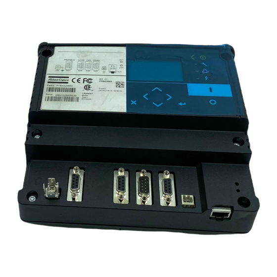
Page 9: Gateway Module
8.2. Gateway module For the Modbus and/or Profibus connection a so-called Gateway module has to be used. This is a general purpose serial communication module. By downloading the correct software, it will perform the proxy and/or bridge function. The following connections will be used: 6x36 : to connect a 24Vac power supply •... -
Page 10: Software Installation And Configuration
Before the module can be used for a Modbus and/or Profibus connection, the correct software application and settings must be downloaded. This can be done by AC Service personnel using AC Speci5. Once the software has been installed, configuration can also be performed by qualified Atlas Copco personnel using AC Modi5. - Page 11 Communication Folder [ Co ] The Communication folder basically offers the possibility to edit the parameters that are used to properly communicate over the CAN channel (with the attached Elektronikon modules on the CAN network), the RS485 Modbus channel and the Profibus channel.
- Page 12 Modbus Parity Below table lists the possible Modbus parities, indicated as follows: Display value Parity None Even Modbus Stopbits Select the number of used stopbits (1 or 2). Profibus Engine The Profibus Engine can be started/stopped here. NOTE: In case the Profibus Engine is active, the settings for Profibus SlaveAddress and Profibus DataRecords are not accessible. Profibus SlaveAddress The Profibus SlaveAddress can be adjusted here.
- Page 13 CAN Engine The CAN Engine can be started/stopped here. NOTE: In case the CAN Engine is active, the setting for CAN Channel is not accessible. CAN Channel Below table lists the possible CAN channels, indicated as follows: Display value Channel Primary Secondary CAN folder [ CA ]...
- Page 14 Password Settings [ PW ] The different password folders offer the possibility to enable/disable and alter the customer password. Program Information [ PI ] The Program Information folder shows information that is associated with the current application. Program Number The Program Number folder shows the program number that is associated with the current application. Program Revision The Program Revision folder shows the program revision number that is associated with the current application.
-
Page 15: Compressors Folder [ Cp ]
9.1.3. Compressors folder [ CP ] The Compressors folder contains 31 subfolders ([CP01] to [CP31]) each containing 2 subfolders, describing the compressor parameters. Information about the icons that are shown in these folders can be found in paragraph 10.1. CAN Status folder [ MA01 ] This parameter defines whether the controller is read-out over CAN. -
Page 16: Gateway Display Description
10. Gateway Display Description 10.1. Icons Icon Description Blinking: Compressor related menu : machine is in CAN Error On: CAN engine stopped Running: CAN engine running Off: Modbus engine stopped On: Modbus engine running Off: Profibus engine stopped On: Profibus engine running On: machine is defined/enabled and is able to request data Blinking: machine is defined/enabled and is able to request settings 10.2. -
Page 17: Passwords / Access Codes
Enter the applicable Access Code 1 digit 3 digits Enter the new Customer Password 3 digits 1 digit Confirm the new Customer Password Access codes are to be requested from Atlas Copco. 13/08/2013 PM 9845 0187 01 Page 17 of 24... -
Page 18: Modbus Protocol Implementation
Function 06 : preset single register • NOTE: for Elektronikon Mk5 controllers, it is not possible to change parameters. Consult the address mapping to check which parameters can be adjusted. 11.3. Function code - data field In a normal response, the slave echoes the function code of the original query. -
Page 19: Exception Codes
11.4. Exception codes Code Name Description Illegal function The function code received in the query is not an allowable action for the slave Illegal Data Address The data address received in the query is not an allowable address for the slave Illegal Data Value A value contained in the query data field is not an allowable value for the slave... -
Page 20: Change The Active Pressure Band
11.5.3. Change the active pressure band Please refer to the Address Mapping document, created by Speci5, to get the correct Register and Value for adjusting the Pressure Band Selection. In this case f.i. the correct Register is 16#03 16#5C. To switch from Pressure Band 1 to Pressure Band 2, value 16#00 16#02 will have to be used. -
Page 21: Profibus Protocol Implementation
12. Profibus Protocol Implementation 12.1. Protocol Specification The protocol is based on the standard Profibus-DP V0 protocol, with the following basic specifications: Mode : RS485 • Baudrate : 9.6k, 19.2k, 45.45k, 93.75k, 187.5k, 500k, 1.5M, 3M, 6M, 12M • Autobaud : Supported •... - Page 22 Alter parameter value (write) NOTE: only one parameter can be written in a cycle, # parameters must be 1 NOTE: for Elektronikon Mk5 controllers, it is not possible to change parameters. Consult the address mapping to check which parameters can be adjusted!
-
Page 23: Data Record
Functions: • Value Function No task, or no data yet Transmit parameter value(s) Task not possible 1,3,4,5,6 Reserved Error code • Value Explanation No error Incorrect number of data records Incorrect function Incorrect number of data records for writing 12.2.2. Data record Each data record is 7 bytes long and contains the following info: Node Address (B1) : 1 byte, CAN Address of slave to connect to. -
Page 24: Examples
12.5. Examples The following examples use the following parameters: Attached module : Mk5 - LU - GA30P_08 • Node ID : • Profibus Slave Address : • Profibus DataRecords : • 12.4.1. Illegal Data Address In case the slave device is asked for a parameter that it is not able to process, the slave device answers with the error code Illegal Data Address.
Need help?
Do you have a question about the Elektronikon Mk5 and is the answer not in the manual?
Questions and answers