Table of Contents
Advertisement
Available languages
Available languages
Advertisement
Chapters
Table of Contents

Related Manuals for Lenze x510


Summary of Contents for Lenze x510
- Page 1 Montage- und Einschaltanleitung | Mounting and switch-on instructions Router IoT Gateway x510 LAN IoT Gateway x520 Wi-Fi IoT Gateway x530 LAN + 4G IoT Gateway x540 LAN + Wi-Fi + 4G Router IoT Gateway x510 LAN IoT Gateway x520 Wi-Fi...
-
Page 3: Table Of Contents
Inhalt Inhalt Über dieses Dokument Weiterführende Dokumente Sicherheitshinweise Grundlegende Sicherheitshinweise Bestimmungsgemäße Verwendung Handhabung Produktinformation Ausstattung Mechanische Installation Abmessungen Montage und Demontage Elektrische Installation Netzanschluss Antennenanschluss SIM-Karte einsetzen Inbetriebnahme Diagnose und Störungsbeseitigung LED-Statusanzeigen Technische Daten Normen und Einsatzbedingungen Bemessungsdaten WiFi-Spezifikationen 4G-Spezifikationen FCC-Erklärung und IC-Erklärung... -
Page 4: Über Dieses Dokument
Diese Anleitung ist für die Produktserie der IoT Gateways x500 gültig. WARNUNG! Lesen Sie diese Dokumentation sorgfältig, bevor Sie mit den Arbeiten beginnen. ▶ Beachten Sie die Sicherheitshinweise! Weiterführende Dokumente Informationen und Hilfsmittel rund um die Lenze-Produkte finden Sie im Internet: www.Lenze.com à Downloads... -
Page 5: Sicherheitshinweise
Sicherheitshinweise Handhabung Sicherheitshinweise Wenn Sie die folgenden grundlegenden Sicherheitsmaßnahmen und Sicherheitshinweise missachten, kann dies zu schweren Personenschäden und Sachschäden führen! Beachten Sie die Vorgaben der beiliegenden und zugehörigen Dokumentation. Dies ist Voraussetzung für einen sicheren und störungsfreien Betrieb, sowie für das Erreichen der angegebenen Produkteigenschaften. Beachten Sie die spezifischen Sicherheitshinweise in den anderen Abschnitten! Grundlegende Sicherheitshinweise Personal... -
Page 6: Produktinformation
Produktinformation Produktinformation Ausstattung IoT Gateway x510 LAN Reset 24-V-Anschluss Digitaler Eingang Status-LED X304 LAN4 (1GBps) X303 LAN3 (1GBps) X302 LAN2 (1GBps) X301 LAN1 (1GBps) X300 Internet/WAN (1GBps) - Page 7 Produktinformation Ausstattung IoT Gateway x520 LAN + Wi-Fi WLAN-Monopolantenne Optional Schraubantenne Reset 24-V-Anschluss Digitaler Eingang Signal-LED Status-LED X304 LAN4 (1GBps) X303 LAN3 (1GBps) LAN2 (1GBps) X302 X301 LAN1 (1GBps) X300 Internet/WAN (1GBps)
- Page 8 Produktinformation Ausstattung IoT Gateway x530 LAN + 4G 4G LTE-Antenne (MAIN) Optional: 4G LTE-Antenne (DIV) SIM-Karte Reset 24-V-Anschluss Digitaler Eingang Signal-LED Status-LED X304 LAN4 (1GBps) X303 LAN3 (1GBps) LAN2 (1GBps) X302 X301 LAN1 (1GBps) X300 Internet/WAN (1GBps)
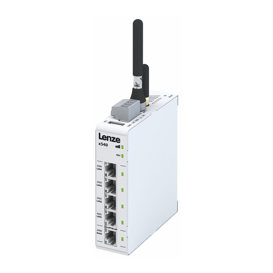
- Page 9 Produktinformation Ausstattung IoT Gateway x540 LAN + Wi-Fi + 4G 4G LTE-Antenne WLAN-Monopolantenne Optional Schraubantenne Reset SIM-Karte 24-V-Anschluss Digitaler Eingang Signal-LED Status-LED X304 LAN4 (1GBps) X303 LAN3 (1GBps) X302 LAN2 (1GBps) X301 LAN1 (1GBps) X300 Internet/WAN (1GBps)
-
Page 10: Mechanische Installation
Mechanische Installation Montage und Demontage Mechanische Installation Abmessungen Die angegebenen Einbaufreiräume sind Mindestmaße, um die ausreichende Luftzirkulation für die Kühlung zu gewährleisten. Sie berücksichtigen nicht die Biegeradien der Anschlussleitungen sowie die aufschraubbaren Antennen bei den Geräten mit Wi-Fi/4G. x520 Montage und Demontage ①... -
Page 11: Elektrische Installation
Elektrische Installation Netzanschluss Elektrische Installation Netzanschluss HINWEIS Falsche Anordnung im Schaltschrank. Fehlfunktion am Gerät. ▶ Beim Einbau in einen Schaltschrank Geräte, die Hochspannung und starke elektromagnetische Störungen erzeugen, von Kleinspannungsgeräten wie dem IoT Gateway x500 trennen. HINWEIS Instabile LAN-Verbindung durch falsche Kabeltypen. Die LAN-Verbindung kann unterbrochen werden. -
Page 12: Antennenanschluss
Elektrische Installation Antennenanschluss Antennenanschluss Nur für IoT Gateways x520, x530 und x540. HINWEIS Mindestabstand bei der Installation beachten. ▶ Die verwendete Antenne muss bei der Installation einen Mindestabstand von 200 mm von Personen haben und darf nicht mit anderen Antennen oder Sendern aufgestellt oder betrieben werden. Das IoT Gateway x530 (LAN + 4G) verfügt über 2 SMA-Antennenanschlüsse. -
Page 13: Sim-Karte Einsetzen
Elektrische Installation SIM-Karte einsetzen Schraubantenne montieren Nachfolgend ist exemplarisch die Montage der RP-SMA Schraubantenne (x5ZAG020000S) am Wi-Fi-Anten- nenanschluss des IoT Gateways x520 dargestellt. 33 ±0.8 SW18 RP-SMA Schraubantenne (x5ZAG020000S) Für den 4G-Antennenanschluss der IoT Gateways x530/x540 ist die LTE-SMA Schraubantenne (x5ZAG040000S) mit identischen Abmessungen erhältlich. -
Page 14: Inbetriebnahme
1. Account erstellen Erstellen Sie einen Account auf der X4 Remote Platform und konfigurieren Sie Ihren eigenen IoT Benutzer- und Firmen-Account unter der Adresse https://iot.lenze.digital/login. 2. IoT Gateway x500 konfigurieren a) Erstellen Sie die Konfigurationsdatei für das IoT Gateway x500 auf Ihrem Account. -
Page 15: Diagnose Und Störungsbeseitigung
Diagnose und Störungsbeseitigung LED-Statusanzeigen Diagnose und Störungsbeseitigung LED-Statusanzeigen Die Status-LED direkt über den LAN-Ports zeigt den aktuellen Status des IoT-Gateways an. Nach dem Einschalten durchläuft das IoT-Gateway verschiedene Zustände, um eine Verbindung zur X4 Remote Platform herzustellen. Der endgültige Status wird nach ca. 2 Minuten signalisiert. Status-LED Zustand/Bedeutung Booten (kann 1 - 2 Minuten dauern)/nicht registriert. -
Page 16: Technische Daten
CSA C22.2 No 60950-1-07 File No. E508568 + Amendment 1 + Amendment 2 Weitere Informationen enthalten unsere Erklärungen und Zertifikate. Diese finden Sie auf der Lenze- Homepage im Download-Bereich zur Technischen Dokumentation des Produkts: www.Lenze.com à Downloads Personenschutz und Geräteschutz... -
Page 17: Wifi-Spezifikationen
Technische Daten FCC-Erklärung und IC-Erklärung WiFi-Spezifikationen x510 x520 x530 x540 Wi-Fi-Version IEEE 802.11 b/g/n IEEE 802.11 b/g/n Wi-Fi-Modi Station (Client) Modus Station (Client) Modus Access Point Access Point Max. Übertragungsrate 72 Mbit/s 72 Mbit/s FCC ID XPYLILYW1 XPYLILYW1 IC ID... - Page 18 Technische Daten FCC-Erklärung und IC-Erklärung...
- Page 19 Contents Contents About this document Further documents Safety instructions Basic safety instructions Application as directed Handling Product information Features Mechanical installation Dimensions Mounting and dismounting Electrical installation Mains connection Antenna connection Installing a SIM card Commissioning Diagnostics and fault elimination LED status display Technical data Standards and operating conditions...
-
Page 20: About This Document
These instructions are valid for the product series of the IoT Gateways x500. WARNING! Read this documentation carefully before starting any work. ▶ Please observe the safety instructions! Further documents Information and tools with regard to the Lenze products can be found on the Internet: www.Lenze.com à Downloads... -
Page 21: Safety Instructions
Safety instructions Handling Safety instructions Disregarding the following basic safety measures and safety information may lead to severe personal injury and damage to property! Observe all specifications of the corresponding documentation supplied. This is the precondition for safe and trouble-free operation and for obtaining the product features specified. Please observe the specific safety information in the other sections! Basic safety instructions Personnel... -
Page 22: Product Information
Product information Product information Features IoT Gateway x510 LAN Reset 24 V connection Digital input Status LED X304 LAN4 (1GBps) X303 LAN3 (1GBps) X302 LAN2 (1GBps) X301 LAN1 (1GBps) X300 Internet/WAN (1GBps) - Page 23 Product information Features IoT Gateway x520 LAN + Wi-Fi WLAN monopole antenna Optional: screw antenna Reset 24 V connection Digital input Signal LED Status LED X304 LAN4 (1GBps) X303 LAN3 (1GBps) LAN2 (1GBps) X302 X301 LAN1 (1GBps) X300 Internet/WAN (1GBps)
- Page 24 Product information Features IoT Gateway x530 LAN + 4G 4G LTE antenna (MAIN) Optional: 4G LTE antenna (DIV) SIM card Reset 24 V connection Digital input Signal LED Status LED X304 LAN4 (1GBps) X303 LAN3 (1GBps) LAN2 (1GBps) X302 X301 LAN1 (1GBps) X300 Internet/WAN (1GBps)
- Page 25 Product information Features IoT Gateway x540 LAN + Wi-Fi + 4G 4G LTE antenna WLAN monopole antenna Optional: screw antenna Reset SIM card 24 V connection Digital input Signal LED Status LED X304 LAN4 (1GBps) X303 LAN3 (1GBps) X302 LAN2 (1GBps) X301 LAN1 (1GBps) X300...
-
Page 26: Mechanical Installation
Mechanical installation Mounting and dismounting Mechanical installation Dimensions The specified installation clearances are minimum dimensions to ensure a sufficient air circulation for cooling purposes. They do not consider the bend radiuses of the connecting cables and screw-on antennas for devices with Wi-Fi/4G. x520 Mounting and dismounting ①... -
Page 27: Electrical Installation
Electrical installation Mains connection Electrical installation Mains connection NOTICE Incorrect arrangement in the control cabinet. Malfunction of the device. ▶ When installing the devices into a control cabinet with a spatial distance, separate the devices that generate high voltage and electromagnetic interference from extra-low voltage devices such as the IoT Gateway x500. -
Page 28: Antenna Connection
Electrical installation Antenna connection Antenna connection For IoT Gateways x520, x530 and x540 only. NOTICE Observe minimum clearance during installation. ▶ The minimum distance from the antenna to persons must be 200 mm and must not be installed or operated together with other antennas or transmitters. IoT Gateway x530 (LAN + 4G) is provided with 2 SMA antenna connections. -
Page 29: Installing A Sim Card
Electrical installation Installing a SIM card Mounting the screw antenna The following example shows how to mount the RP-SMA screw antenna (x5ZAG020000S) to the Wi-Fi antenna connection of the IoT Gateway x520. 33 ±0.8 SW18 RP-SMA screw antenna (x5ZAG020000S) For the 4G antenna connection of the IoT Gateways x530/x540 the LTE-SMA screw antenna (x5ZAG040000S) is available with identical dimensions. -
Page 30: Commissioning
1. Create account Create an account on the X4 Remote Platform and configure your own IoT user and company account at https://iot.lenze.digital/login. https://iot.lenze.digital/login. 2. Configure IoT Gateway x500 a) Create the configuration file for the IoT Gateway x500 on your account. -
Page 31: Diagnostics And Fault Elimination
Diagnostics and fault elimination LED status display Diagnostics and fault elimination LED status display The status LED directly above the LAN ports shows the current status of the IoT Gateway. After switching on, the IoT Gateway passes through various states to establish a connection to the X4 Remote Platform. -
Page 32: Technical Data
File No. E508568 + Amendment 1 + Amendment 2 Our declarations and certificates contain further information. These can be found on the Lenze homepage in the download area of the technical documentation of the product: www.Lenze.com à Downloads Protection of persons and device protection... -
Page 33: Wifi Specifications
Technical data FCC statement and IC statement WiFi specifications x510 x520 x530 x540 Wi-Fi version IEEE 802.11 b/g/n IEEE 802.11 b/g/n Wi-Fi modi Station (Client) Mode Station (Client) Mode Access Point Access Point Max. baud rate 72 Mbps 72 Mbps... - Page 34 © 03/2020 | 13580249 | 1.0 Lenze Automation GmbH Postfach 101352, 31763 Hameln Hans-Lenze-Str. 1, 31855 Aerzen GERMANY HR Hannover B 205381 Phone +49 5154 82-0 Fax +49 5154 82-2800 sales.de@lenze.com www.Lenze.com Lenze Service GmbH Breslauer Straße 3, 32699 Extertal...
Need help?
Do you have a question about the x510 and is the answer not in the manual?
Questions and answers