Table of Contents
Advertisement
Quick Links
our name is our principle
UV-
TECHNOLOGY
Technical Documentation
®
®
®
ELC
N6 / ELC
N8 / ELC
N10
GB
eta plus electronic gmbh
Lauterstraße 29, D-72622 Nürtingen, Telefon +49 (0) 70 22 - 60 02-80, Fax +49 (0) 70 22 – 6 58 54
Postfach 1411, D-72604 Nürtingen, e-mail: info@eta-uv.de
eta plus electronic gmbh
––––––––––––––––––––––––––––
Lauterstraße 29, 72622 Nürtingen, Telefon +49 7022 6002-80, Fax +49 7022 65854, E-mail: info@eta-uv.de, www.eta-uv.de
Eingetragen unter HRB 724321 AG Stuttgart, USt.-Id.-Nr. DE 146267800
Eingetragen unter HRB 724321 AG Stuttgart, USt.-Id.-Nr. DE 146267800, Geschäftsleitung: Uwe Uhlemann, Dr. Markus Roth
Geschäftsführer: Dr. Peter Schwarz-Kiene
Advertisement
Table of Contents

Summary of Contents for Metz Eta Plus ELC N6
- Page 1 our name is our principle TECHNOLOGY Technical Documentation ® ® ® N6 / ELC N8 / ELC eta plus electronic gmbh Lauterstraße 29, D-72622 Nürtingen, Telefon +49 (0) 70 22 - 60 02-80, Fax +49 (0) 70 22 – 6 58 54 Postfach 1411, D-72604 Nürtingen, e-mail: info@eta-uv.de eta plus electronic gmbh ––––––––––––––––––––––––––––...
- Page 2 ® („Electronic Lamp Control“) is a registered trademark of IST Metz GmbH. ELC N6_N10-V3.1-09/11-GB subject to technical alterations...
-
Page 3: Table Of Contents
Contents page I Contents 1 Safety ....................1 1.1 Definition of Symbols .................1 1.2 Safety Advice ....................1 1.3 Correct operation..................2 1.4 Extended use ....................2 2 Description of functions..............3 3 Installation ..................4 3.1 Mounting of casing ..................4 3.1.1 Back mounting ....................5 3.1.2 Side by side rack mounting................ -
Page 4: Safety
Safety page 1 Safety Definition of Symbols Stop (Stop Danger). This symbol warns of serious danger of severe injury to persons. It must be strictly observed. Attention (Warning). This symbol indicates information the non-observance of which can lead to extensive damage to property. The safety warning must be strictly observed. -
Page 5: Correct Operation
Safety page 2 The ELC causes a leakage current greater than 3.5 mA! Safeguarding by means of leakage current protection type A and type AC according to IEC 60755 is not permitted! The ELC operates in principle as a frequency converter and is equipped with a mains filter whose leakage current could activate fuse protection. -
Page 6: Description Of Functions
Description of functions page 3 Description of functions The electronic ballast ELC is designed to operate medium pressure discharge lamps as described in chapter 6. In contrast to conventional ballasts (inductive lamp ballast or transformer or transformer with transductor), the lamp with an electronic ballast is operated with high frequency (approx. 100 kHz). -
Page 7: Installation
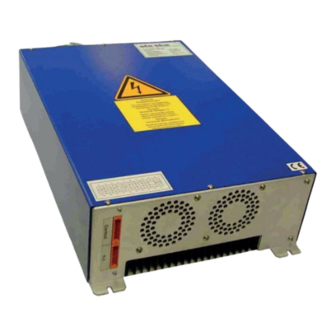
Installation page 4 Installation Mounting of casing The ELC must be installed in a control cabinet with at least IP 54 protection (see EN 60529). Operation without a control cabinet or in a control cabinet with a lower degree of protection is not permitted. The ELC may only be installed vertically (control connections at the bottom, power connection at the top) allowing for at least the minimum spacing as shown. -
Page 8: Back Mounting
Installation page 5 3.1.1 Back mounting min. 20 min. 20 pin-and-socket connector for control signals Assembly for instance by gudgeon M6 with distance sleeve 23 mm 270 mm 23 mm Lamp feeder cable mains connection 319 mm Fig. 1: Assembly of the ELC (all dimensions in mm). ELC N6_N10-V3.1-09/11-GB subject to technical alterations... -
Page 9: Side By Side Rack Mounting
Installation page 6 3.1.2 Side by side rack mounting pin-and-socket connector for control signals M8 (4x) 23 mm 80 mm Lamp feeder connection mains connection 321 mm Fig. 2 side by side rack mounting with assembly brackets ELC N6_N10-V3.1-09/11-GB subject to technical alterations... - Page 10 Installation page 7 If “side-by-side rack mounting“ is preferred, assembly brackets and screws can be provided upon request. Attach bracket to the upper surface of the appliance Attach bracket to the underside of the appliance ELC N6_N10-V3.1-09/11-GB subject to technical alterations...
-
Page 11: Connection
Installation page 8 Connection The power connections of the ELC are situated on top of the casing. earthed lead network side Fig. 3 shows the electrical automatic cutout wiring plan. L1 L2 lamp feeder cable shielding must be connected to out1 out2 the ELC. - Page 12 Installation page 9 Mains connection The mains connection of the ELC is situated at the top right. The cross section of the earthed wire must be at least 4 mm². The three phases must be provided with an automatic cut-out. Fig.
- Page 13 Installation page 10 Connecting the lamp feeder cable The lamp feeder cable must correspond with the cable parameters described in chapter Technical Data. Connector assembly (from left to right) • Carrier casing • Casing gasket • Hood and screws • EMC cable gland with plastic insert Preparing the lamp feeder cable: •...
- Page 14 Installation page 11 • Do not twist wires additionally • Insert wires into the contact chamber so that the insulation is aligned with the tightening nut. • When tightening the nut hold the wire in position. Torque: 1Nm (permissible moment für screw driver =1.2 Nm) Hexagon socket (jaw span 2) •...
-
Page 15: Control Current Connections
Installation page 12 • Tighten EMC cable gland The lamp feeder cable between the switch cabinet and lamp assembly must be laid in a metal insulating tube. For the correct installation of the lamp assembly and lamp please observe the corresponding manufacturer’s instructions. Control current connections The control wires are connected to the underside of the casing by means of the connectors. - Page 16 Installation page 13 Designation Pin No. Description 15 - 30 V AC / DC, between Pin 1 and Pin 20 digital control input Start1 input impedance = 1 kΩ START Start2 potential-free, active high 15 - 30 V AC / DC, between Pin 2 and Pin 19 digital control input Max1 input impedance = 1 kΩ...
-
Page 17: Explanations Of The Control Functions For Elc
Installation page 14 Explanations of the control functions for ELC 3.4.1 Release relay The release relay indicates the trouble-free operation of the unit. This means that the relay closes when the ELC (see 4.2) is switched on and remains closed during operation providing there is no defect. - Page 18 Installation page 15 Digital: MIN und MAX For certain operation modes the lamp power can be set to Maximum or Minimum independent of the control voltage at SET VALUE. E.g.: • Lamp warm-up: maximum power or • Standby operation: minimum power To this purpose the control inputs MAX and MIN respectively are set to High, whereby the function MAX has the higher priority.
-
Page 19: Earth Fault Control
Installation page 16 3.4.5 Earth fault control The ELC (electronic ballast) has been fitted with an earth fault control system. The ELC is fitted with an earth fault relay ES for the purpose of indicating an earth fault. During trouble-free operation the relay is closed (provided the ELC is connected to the power supply voltage). -
Page 20: Operation Of Elc
Operation of ELC page 17 Operation of ELC Initial operation The operative parameters of the ELC, such as the scope of the trigger pulse when switching on the lamp, is set by the manufacturer. Alterations to the manufacturer’s settings can only be carried out by the manufacturer. -
Page 21: Dimming Operation
Operation of ELC page 18 Dimming Operation After having reached nominal operation, the desired lamp power can be infinitely adjusted. • Lamp power is adjusted via control voltage (0 – 10 V) at the analogous SET VALUE control input. In this context, 0 V are tantamount to minimum and 10 V to maximum lamp power. The adjustment of lamp power via the analogous SET VALUE control input is only possible if a LOW signal is applied to the digital MIN and MAX control inputs. -
Page 22: Troubleshooting
Troubleshooting page 19 Troubleshooting Troubles Possible causes Corrective action No RELEASE after having The ELC is not provided Check fuses and voltage of switched on the ELC. with operating voltage terminals Relay RELEASE open Lamp is switched-ON Switch-OFF lamp (control input START at HIGH) Fault in ELC Contact manufacturer,... -
Page 23: Technical Data
Technical Data page 20 Technical Data General data ELC mains frequency 50 / 60 Hz tolerance mains voltage nominal voltage ± 10 % recommended air flow 120 m / h per ballast Control range approx. 20 - 100 % Firing voltage 2000 V / <... - Page 24 Technical Data page 21 Type specific data Type N6-400-75 N6-480-75 N8-400-80 N8-480-80 N10-400-80 N10-480-80 Power factor typ. 0,95 typ. 0,94 typ. 0,94 typ. 0,94 typ. 0,94 typ. 0,94 Power efficiency typ. 0,96 typ. 0,95 typ. 0,96 typ. 0,95 typ. 0,96 typ.
Need help?
Do you have a question about the Eta Plus ELC N6 and is the answer not in the manual?
Questions and answers