Raycap PowerPlus System 100-3-1U Series Installation Instructions Operations Manual
Hide thumbs
Also See for PowerPlus System 100-3-1U Series:
- Installation instructions operations manual (32 pages) ,
- Installation instructions operations manual (36 pages)

Related Manuals for Raycap PowerPlus System 100-3-1U Series


Summary of Contents for Raycap PowerPlus System 100-3-1U Series
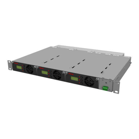
- Page 1 PowerPlus System 100-3-1U INSTALLATION INSTRUCTION & OPERATION MANUAL INSTALLATION INSTRUCTION & OPERATION MANUAL PowerPlus System 100-3-1U Series 100-3-1U-3 100-3-1U-2 www.raycap.com...
-
Page 3: Table Of Contents
Initial Settings Menu: Mode Selection .....................18 Parallel Mode Settings ..........................18 10. Single Mode Settings ..........................21 11. Live Settings Menu ...........................24 12. Bus Bar ..............................26 13. Alarms ...............................27 © Raycap | All rights reserved. • (320-1398) QRC | Rev.A www.raycap.com Page 1 of 34... -
Page 4: Copyright
Disclaimer The information in this document is subject to change without notice and describes only the product defined in the introduction of this documentation. This documentation is intended for the use of Raycap customers only for the purposes of the agreement under which the document is submitted, and no part may be used, reproduced, modified or transmitted in any form or means without the prior written permission of Raycap. The documentation has been prepared to be used by professional and properly trained personnel, and the customer assumes full responsibility when using it. -
Page 5: Introduction
® protection at the RRH and BBU. PowerPlus is Raycap’s solution for an intelligent and dynamic power transmission to the RRH units of a DAS Telecommunication site. PowerPlus is a system installed at the PSU output that increases the voltage at the base of a cellular site to compensate the voltage drop on the DC power cables that provide power to the RRHs. -
Page 6: Mounting
23" rack. Mount the unit on the rack. Release the 4 push pins and remove touch guard as shown below. (320-1398) QRC | Rev.A • © Raycap | All rights reserved. www.raycap.com Page 4 of 34... -
Page 7: General Description
• The voltage output of each module may be connected to an individual load when the device is configured to operate in Single Mode. • The outputs of the modules may be connected in parallel when the device is configured to operate in Parallel Mode. In this configuration, the load is shared among each of the installed modules. © Raycap | All rights reserved. • (320-1398) QRC | Rev.A www.raycap.com Page 5 of 34... -
Page 8: System Topology
PowerPlus System 100-3-1U INSTALLATION INSTRUCTION & OPERATION MANUAL System Topology -48VDC -48VDC -48VDC -48VDC OUT 1 OUT 2 OUT 3 (320-1398) QRC | Rev.A • © Raycap | All rights reserved. www.raycap.com Page 6 of 34... -
Page 9: Installation Configurations
INSTALLATION INSTRUCTION & OPERATION MANUAL Installation Configurations SINGLE -48VDC OUT 3 -48VDC -48VDC OUT 2 -48VDC OUT 1 RTN OUT PARALLEL -48VDC -48VDC OUT RTN OUT PowerPlus 100-3-1U system configurations © Raycap | All rights reserved. • (320-1398) QRC | Rev.A www.raycap.com Page 7 of 34... -
Page 10: Module Configurations
Use 6 gauge copper wire for ground -48V -48V Return Return GROUND Power Plus 100 AMP Module Installed RTMDC-5634-PF-48 RNSNDC-7771-PF-48 RTMDC-4983-RM-48 Trunk to Upper OVP (320-1398) QRC | Rev.A • © Raycap | All rights reserved. www.raycap.com Page 8 of 34... - Page 11 -48V -48V Return Return GROUND Power Plus 100 AMP 100 AMP Module Module Installed Installed RTMDC-5634-PF-48 RNSNDC-7771-PF-48 RTMDC-4983-RM-48 Trunk to Upper OVP © Raycap | All rights reserved. • (320-1398) QRC | Rev.A www.raycap.com Page 9 of 34...
- Page 12 -48V -48V Return Return GROUND Power Plus 100 AMP 100 AMP Module Module Installed Installed RTMDC-5634-PF-48 RNSNDC-7771-PF-48 RTMDC-4983-RM-48 Trunk to Upper OVP (320-1398) QRC | Rev.A • © Raycap | All rights reserved. www.raycap.com Page 10 of 34...
- Page 13 Return Return GROUND Power Plus 100 AMP 100 AMP 100 AMP Module Module Module Installed Installed Installed RTMDC-5634-PF-48 RNSNDC-7771-PF-48 RTMDC-4983-RM-48 Trunk to Upper OVP © Raycap | All rights reserved. • (320-1398) QRC | Rev.A www.raycap.com Page 11 of 34...
- Page 14 Return Return GROUND Power Plus 100 AMP 100 AMP 100 AMP Module Module Module Installed Installed Installed RTMDC-5634-PF-48 RNSNDC-7771-PF-48 RTMDC-4983-RM-48 Trunk to Upper OVP (320-1398) QRC | Rev.A • © Raycap | All rights reserved. www.raycap.com Page 12 of 34...
-
Page 15: System Management
The primary module in the parallel mode will display the input and output voltage of the system. The • secondary modules will display “Module 1” and “Module 2” messages. Parallel Primary Parallel Secondarys © Raycap | All rights reserved. • (320-1398) QRC | Rev.A www.raycap.com Page 13 of 34... -
Page 16: Module Failure
• The alarm will disappear after pressing the ‘ENTER’ button on the current Primary module for more than 3 seconds. (320-1398) QRC | Rev.A • © Raycap | All rights reserved. www.raycap.com Page 14 of 34... -
Page 17: Modules
Modules Module Replacement • Unscrew the thumb screws on both sides of module. • Release the side levers out. • Pull out the device. © Raycap | All rights reserved. • (320-1398) QRC | Rev.A www.raycap.com Page 15 of 34... -
Page 18: Cold Module Replacement
“REMOVE MODULE” and the invalid module must be removed. • If there is a cold module installation in open slot(s) (in either operational mode i.e. parallel/single), then the system will prompt for initial settings during power on. (320-1398) QRC | Rev.A • © Raycap | All rights reserved. www.raycap.com Page 16 of 34... -
Page 19: Module Settings
Slot 2 Slot 3 • The primary module is selected by pressing the ‘ENTER’ button of any module (e.g. Slot 1 module). This module will become the primary module and the other modules will be configured as secondary modules. ENTER © Raycap | All rights reserved. • (320-1398) QRC | Rev.A www.raycap.com Page 17 of 34... -
Page 20: Initial Settings Menu: Mode Selection
The secondary modules (Slot 2, Slot 3) in this stage will display “SETTINGS OK” since they are waiting for common settings from the primary module. Up/Down Slot 2 Slot 3 Slot 1 Primary (320-1398) QRC | Rev.A • © Raycap | All rights reserved. www.raycap.com Page 18 of 34... - Page 21 The system then calculates 2X this cable length to account for the return and -48V cable runs. Slot 2 Slot 3 Up/Down +/-1ft Up/Down +/-1m Slot 1 Slot 1 Primary Imperial Primary Metric © Raycap | All rights reserved. • (320-1398) QRC | Rev.A www.raycap.com Page 19 of 34...
- Page 22 It then starts the main parallel mode operation cycle. Slot 1 Slot 2 Slot 3 Primary Main Parallel Mode Operation Slot 1 Slot 2 Slot 3 Primary (320-1398) QRC | Rev.A • © Raycap | All rights reserved. www.raycap.com Page 20 of 34...
-
Page 23: Single Mode Settings
‘UP’ or ‘DOWN’ buttons of the primary module. The selection is applied by pressing the ‘ENTER’ button of the primary module. Up/Down Up/Down Slot 2 Slot 3 Slot 1 Slot 1 Primary Imperial Primary Metric © Raycap | All rights reserved. • (320-1398) QRC | Rev.A www.raycap.com Page 21 of 34... - Page 24 -54V. Top voltage target value below -58V (-59V or -60V) could cause eventually RRU high voltage alarms and is not recommended. Up/Down +/- 1V Slot 1 Slot 2 Slot 3 (320-1398) QRC | Rev.A • © Raycap | All rights reserved. www.raycap.com Page 22 of 34...
- Page 25 Finish • When all modules have been configured, the system starts the single mode operation cycle. Slot 1 Slot 2 Slot 3 Primary Main Single Mode Operation Slot 1 Slot 2 Slot 3 Primary © Raycap | All rights reserved. • (320-1398) QRC | Rev.A www.raycap.com Page 23 of 34...
-
Page 26: Live Settings Menu
‘UP’ or ‘DOWN’ buttons of the primary module. The selection is applied by pressing the ‘ENTER’ button of the Primary module. Up/Down Slot 2 Slot 3 Slot 1 Primary (320-1398) QRC | Rev.A • © Raycap | All rights reserved. www.raycap.com Page 24 of 34... - Page 27 New/Previous Configuration selection and the next step for the primary is the mode selection. • From this point the modules can be configured independently with the same proceeding steps as the initial settings menu. Slot 1 Slot 2 Slot 3 Primary Slot 1 Slot 2 Slot 3 Primary © Raycap | All rights reserved. • (320-1398) QRC | Rev.A www.raycap.com Page 25 of 34...
-
Page 28: Bus Bar
If the system is in single mode and the bus bar is connected, the system is will display • “REMOVE BUS BAR” message. The bus bar must be removed when single mode is selected. (320-1398) QRC | Rev.A • © Raycap | All rights reserved. www.raycap.com Page 26 of 34... -
Page 29: Alarms
13.2 NOTE: Secondary Module Failure is detailed in the System Management section of this document. Primary Module Failure is detailed in the System Management section of this document. © Raycap | All rights reserved. • (320-1398) QRC | Rev.A www.raycap.com... - Page 30 ‘HIGH CURRENT’ message. The secondary will detect the stopped primary and take control as the new primary module. The new primary will raise a primary failure alarm. Halted Primary Module New Primary Module (320-1398) QRC | Rev.A • © Raycap | All rights reserved. www.raycap.com Page 28 of 34...
- Page 31 ‘RRU VLT HIGH’ message in case that this condition remains for more than 3 seconds. The alarm is cleared by when the RRV‘s input voltage decreases to normal level. © Raycap | All rights reserved. • (320-1398) QRC | Rev.A www.raycap.com...
- Page 32 The new primary will raise a primary failure alarm. Halted Primary Module New Primary Module (320-1398) QRC | Rev.A • © Raycap | All rights reserved. www.raycap.com Page 30 of 34...
- Page 33 When there is a sort circuit at the output of a module for more than 20msec then the module will display a “DC/DC ALERT” message. The module will be halted in order to avoid any damage for the device. 13.11 Module DC/DC Converter Communication Failure • In case that there is a communication failure between module and internal DC/DC converter then the module will be halted and will display a ‘DC/DC COM FAIL’ message. © Raycap | All rights reserved. • (320-1398) QRC | Rev.A www.raycap.com Page 31 of 34...
- Page 34 PowerPlus System 100-3-1U INSTALLATION INSTRUCTION & OPERATION MANUAL Notes (320-1398) QRC | Rev.A • © Raycap | All rights reserved. www.raycap.com Page 32 of 34...
- Page 36 PowerPlus System 100-3-1U INSTALLATION INSTRUCTION & OPERATION MANUAL (320-1398) QRC | Rev.A • © Raycap | All rights reserved. www.raycap.com Page 34 of 34...
Need help?
Do you have a question about the PowerPlus System 100-3-1U Series and is the answer not in the manual?
Questions and answers