
Related Manuals for Datum Storage Ez2


Summary of Contents for Datum Storage Ez2
- Page 1 Ez2 Assembly Instructions If you need assembly assistance, please contact Customer Service at: 1-866-217-0330 (Monday thru Friday 8:00 A.M. - 5:00 P.M. E.S.T.) Page 1...
- Page 2 Ez2 Assembly Instructions (Tube of Thread Adhesive Included Hardware: Not Shown) (Full Scale) 1/4-20 x 3/4" 1/4-20 x 5/8" Phillips 1/4-20 x 1/2" Phillips Countersink Allen Pan Head Screw Pan Head Screw Flat Head Screw #10 x 3/8" Phillips #8 x 1/2" Phillips...
- Page 3 Ez2 Assembly Instructions Parts Base Assembly Top Cover of Rotating Cabinet Side Front/Rear Front/Rear Side Side Panel (Qty 2) Left Upright Right Upright Right Upright (Qty 2) w/Lock Plug w/Lock Page 3...
- Page 4 Ez2 Assembly Instructions Parts Shelf Top Cover Edge Guard End Panel (Qty 4) (Optional) Divider Cabinet Divider Page 4...
- Page 5 Ez2 Assembly Instructions Figure A Left Upright Base Step 1: Using provided 5/32" allen wrench, attach a left upright to the base with two 1/4-20 x 3/4 Flat Countersink Allen Cap Screws (see Figure A and Detail B). Front of Unit...
- Page 6 Ez2 Assembly Instructions Figure C Right Upright w/Lock Step 2: Attach right upright with lock to base with two 1/4-20 x 3/4 Flat Countersink Allen Cap Screws (see Figure C and Detail D). Left Upright Step 3: Repeat Steps 1 & 2 for the rear of the unit.
- Page 7 Ez2 Assembly Instructions Figure F Shipping Bolts Step 4: Remove two shipping bolts from top of base with a Phillips Head Screwdriver (see Figure F and Detail G). CAUTION: After removing shipping bolts, be careful not to tilt unit as bearings may become dislodged.
- Page 8 Ez2 Assembly Instructions Figure L Apply dab of lock adhesive in hole Spacer Step 6: Apply a dab of lock adhesive in cam hole. Push one 3/8" shoulder bolt through lock bar and spacer tube, attach to lock cam. Tighten with 3/32" allen wrench 3/16"...
- Page 9 Ez2 Assembly Instructions Figure N Side Panel Step 8: Attach first side panel with four #10 x 3/8" Phillips Pan Head Screws. The side panel will fit onto the spinning base as shown in Figure N and Detail P. ATTENTION: Support side panel so it does not tip over and damage unit.
- Page 10 Ez2 Assembly Instructions Figure S Step 10: DO NOT TIGHTEN SCREWS DURING THIS STEP!!! (Leave an 1/8" gap between head of screw and surface of metal)Fasten four #10-24 x 1/2" Type 'F' Phillips Pan Head Screws to each side panel as shown in Figure S and Detail T.
- Page 11 Ez2 Assembly Instructions Top Cover Step 12: Position top cover as shown in Figure V. Make sure that shaft on top cover goes into hub on top of rotating section. Fasten top cover to uprights with a total of eight #10 x 3/8" Phillips Pan Head Screws.
- Page 12 Ez2 Assembly Instructions Figure Y NOTE: For standard filing applications, a small indicator hole can be found next to each standard shelf hole (see Detail Z). This will allow for equal shelf openings and in most cases, it will leave enough space for a posting shelf.
- Page 13 Ez2 Assembly Instructions Shelf Side Panel #10-24 x 1/2" Figure AA Screw Figure AB Shelf Side Panel Step 15: To install shelf, position shelf so it hooks on to front two mounting screws (Figures AA & AB), then push shelf in and tip it down so rear of shelf hooks on to rear two screws (Figure AC).
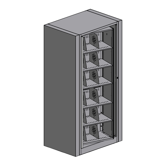
- Page 14 Ez2 Assembly Instructions Note: Figure AD Unit shown consists of one starter and one add-on unit. End Panel *Inside of cabinet not shown for clarity. End Panel Should Have Tinnerman Nuts Attached 1/4-20 Nut 1/4-20 x 5/8 Screw 1/4-20 x 5/8...
- Page 15 Ez2 Assembly Instructions Divider Figure AG Shelf Step 18: To install dividers, insert front tab first (Figure AG). Then insert rear two tabs (Figures AH). Two dividers per shelf. Divider Figure AH Shelf Page 15...
- Page 16 Ez2 Assembly Instructions Figure AJ Step 19: Attach edge guards to the four uprights. Edge guards attach by simply pressing them on short flange of each upright (Detail AK). Detail AK Top Cover Upright Figure AL Edge Guard Upright Edge Guard...
- Page 17 Ez2 Assembly Instructions Figure AM Detail AN Step 20: To level the unit, use a 3/16" Nut Driver to adjust the four leveling glides from the access holes in top of base (see Detail AN). Access Hole for Leveling Page 17...
Need help?
Do you have a question about the Ez2 and is the answer not in the manual?
Questions and answers