Table of Contents
Advertisement
Advertisement
Table of Contents

Related Manuals for Micron MC-20

Summary of Contents for Micron MC-20
- Page 1 MC-20 Fastening Attaching Machine User Manual VERSION 1.02...
-
Page 2: Table Of Contents
Technical Data (Double) Scope and Purpose Setup Process Overview Setup Process Procedures Assembling the Table and Mounting the MC-20 Remove all the contents of the box and layout and floor Assembling the Lengs Securing the Table Top to the Legs... - Page 3 MC-20 User Manual / Table of Contents Turning the Machine On and Emergency Stop Button Turning the Machine On and Emergency Stop Button 22 - 23 Air Pressure Setting Air Pressure Power and Setting 24 -25 Fuse System Fuse System...
-
Page 4: Technical Data (Single)
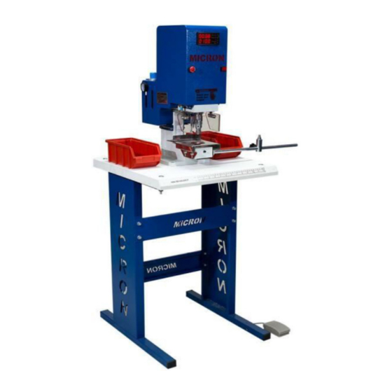
A laser guidance system that marks the grommet setting point. All types and sizes of Eyelets, Spring Snaps, Ring Snaps, Jean Rivets and Jean Buttons. The digital panel of the MC-20 displays installed fastener count, and piston stroke settings. Laser guidance system VIDEOS Installing Grommets In To Shower Curtain Material https://vimeo.com/125072496... -
Page 5: Technical Data (Double)
A laser guidance system that marks the grommet setting point. All types and sizes of Eyelets, Spring Snaps, Ring Snaps, Jean Rivets and Jean Buttons. The digital panel of the MC-20 displays installed fastener count, and piston stroke settings. Laser guidance system VIDEOS Industrial Metal Hole Piercing Die Installation https://vimeo.com/240897840... -
Page 6: Scope And Purpose
This manual is intended to be used during the initial setup of the MC-20, making the first installations and to help troubleshoot problems you may face over the life of the machine. -
Page 7: Assembling The Table And Mounting The
Assembling the Table and Mounting the MC-20 The following procedure will guide you through setting up the table and mounting the MC-20. You will need a set of Allen keys and a set of pliers or the corresponding wrench size for the nuts. -
Page 8: Assembling The Lengs
Assembling the Legs 1. Stand both legs perpendicular to the floor and hold one of the cross bars between the two. (Ensure “Micron” is oriented properly) 2. Align the holes on the cross bar to those of the legs. 3. Insert the short bolts from front to back and secure them with the nuts. -
Page 9: Securing The Table Top To The Legs
MC-20 User Manual / Setup Process Procedures Securing the Table Top to the Legs 1. Place the table on top of the two legs. Ensure that the holes on the legs align with those of the table. 2. Drop the four long bolts through the table and leg holes. -
Page 10: Unboxing The
User Manual / Setup Process Procedures Unboxing the MC-20 1. The box containing the MC-20 must first have the protective cover removed. 1.1 Unscrew all the screws that border the bottom of the box. 1.2 Carefully lift the cover up and off of the machine. -
Page 11: Securing The Mc-20 To The Table
MC-20 User Manual / Setup Process Procedures Securing the MC-20 to the Table 3. Unbolt the machine from the base board. Place the bolts to the side for now. 11/37... - Page 12 4. Carefully place the machine onto the assembled table. Ensure that the holes on the machine where the bolts were removed and the table’s holes are aligned. 5. Bolt the MC-20 onto the table with the bolts that were placed to the side. 6. The table and machine are now fully assembled.
-
Page 13: Mc-20 Pneumatic, Electrical And Foot Pedal Connections
This end is then inserted into the air compressor according to the manufacturer’s instructions. 3. Turn the lever where the hose is inserted into the MC-20 so that it is parallel to the fittings. This will allow air to flow into the machine. -
Page 14: Connecting To An Outlet
MC-20 User Manual / Pneumatic, Electrical and Foot Pedal Connections Connecting to an Outlet 1. Unwrap the electrical cable that is within the small white box. 2. Insert the female end of the electrical cable into the rear of the machine. -
Page 15: Connecting The Foot Pedal
MC-20 User Manual / Pneumatic, Electrical and Foot Pedal Connections Connecting the Foot Pedal 1. The foot pedal has a special grove that will correlate to the grove in the port on the machine. 1. The port is located on the right hand side of the machine, towards the rear. -
Page 16: Installing Dies And Adapters With Dies
In this section, the installation of dies and adapters with dies will be covered. The MC-20 can accommodate 2 sizes and styles for both the top insert and bottom insert. Regardless of the dies that were purchased, your machine will come with adapters. - Page 17 MC-20 User Manual / Installing Dies and Adapters with Dies Slide the bottom die adapter into the bottom opening. Be sure to position the slit perpendicular to the lower tension screw. Your machine may have the bottom tension screw on the front or on the side.
- Page 18 MC-20 User Manual / Installing Dies and Adapters with Dies Use an Allen key to tightly secure both the adapter and bottom die into the machine. 18/37...
- Page 19 MC-20 User Manual / Installing Dies and Adapters with Dies 3. Slide the upper die adapter up into the mill ensuring that the flattened portioned is aligned with one of the two tension screws. 4. Use an Allen wrench to tightly secure the adapter.
-
Page 20: Installing Dies Without Adapters
MC-20 User Manual / Installing Dies and Adapters with Dies Installing Dies without Adapters 1. Slide the bottom die into the bottom slot of the machine. If your bottom die has a flat portion on it, ensure that this side is facing the tension screw. -
Page 21: Securing Industrial Dies
MC-20 User Manual / Installing Dies and Adapters with Dies 1. Slide the upper die up into the mill ensuring that the flattened portioned is aligned with one of the two tension screws. 2. Use an Allen wrench to tightly secure the upper die in place. -
Page 22: Turning The Machine On And Emergency Stop Button
MC-20 User Manual / Turning the Machine On and Emergency Stop Button Turning the Machine On and Emergency Stop Button This section covers turning on the machine and operating the emergency stop button. 1. The power switch is located at the back of the machine. On the left, the machine is in the off position;... - Page 23 MC-20 User Manual / Turning the Machine On and Emergency Stop Button The emergency stop button is located at the front of the machine on the left. It should only be used in emergencies. The proper way to turn the machine off is with the power switch at the back of the machine.
-
Page 24: Air Pressure Power And Setting
The air intake pressure control valve will adjust the piston pressure from 0-150 PSI (0-10 bar). Stroke up/down keys on the digital panel will adjust the piston stroke from 0-150. The MC-20 is capable of applying up to 950 kg of pressure per square centimeter. - Page 25 They are stroke setting and air pressure setting. AIR PRESSURE SETTING: In the back of the MC-20 on the right hand side you will find the air pressure gage. The red numbers from 2 through 10 indicate the “BAR”...
-
Page 26: Fuse System
MC-20 User Manual / Fuse System Fuse System The machine’s fuse can be found at the back of the machine near the socket for the electrical cord. To check to see if the is power going into the machine. Remove the back plate, plug in the machine and if you peer inside you should see a green LED light. -
Page 27: General Meintenance
MC-20 User Manual / General Maintenance General Maintenance 1- Set screws(C) should be checked on daily maintenance. 2- Security cover connection and setting plate screws (B) should be checked on weekly maintenance. 3- Main piston and security pistons (A) should be lubrified with grease oil on monthly maintenance. -
Page 28: Filter Cleaning Process
MC-20 User Manual / General Maintenance Filter Cleaning Process 1- Please switch the machine air inlet valve to on position. 2- Please push the filter cleaning pin up with a screwdriver. 3- Please provide the air discharge for a while. Then you will see that air in tank will be cleaned. -
Page 29: Oil Filling Process
MC-20 User Manual / General Maintenance Oil Filling Process 1- Please switch machine air inlet valve off and ensure the air discharge by pressing machine start button a few times. 2- Take out the oil filter plug (A) with compatible screwdriver by loosening. -
Page 30: Resetting Safety System
MC-20 User Manual / General Maintenance Resetting Safety System https://vimeo.com/123454940 the video is not in English; I have written step by step directions according to the instructions in the video. Please view the video and follow the instructions stated below for resetting the safey system in your machine,... -
Page 31: Air Leak Problems
This problem typically occurs if proper procedure is not followed while adjusting the air pressure on an MC-20 machine and is typically easy to fix. If the steps outlined in this email do not solve your air leak problem, we will need to order your part from our factory in Turkey;... -
Page 32: Start Button & Mill Problem
MC-20 User Manual / Setup Process Procedures Start Button & Mill Problem 1- First check that the hose is securely connected to the machine. 2- Ensure that the valve is in the open position and the gauge shows that air is entering the machine. - Page 33 MC-20 User Manual / Setup Process Procedures 3- Turn the machine on. 4- Test the start button. If the machine does not fire the safety and main pistons, you will need to check to see if any of the hoses on the inside are pinched. Remove the back plate by unscrewing the four bolts that secure it to the body of the machine.
-
Page 34: Instruction Of The Screen Operation
MC-20 User Manual / Instruction Instruction of the Screen Operation 34/37... -
Page 35: Schematic Diagram
MC-20 User Manual / Instruction Schematic Diagram 35/37... -
Page 36: Safety Pistons Connection Diagram
MC-20 User Manual / Instruction Safety Pistons Connection Diagram 36/37... -
Page 37: Contact Informations
Always turn off the machine and air when you change the dies. MC-20 Fastener Attaching Machine shipped to you was tooled and tested using a specific grommet as indicated on the identification tag fastened to the machine. It may be dangerous to use this machine for any assembly or purpose other than that for which it was originally designed and built.
Need help?
Do you have a question about the MC-20 and is the answer not in the manual?
Questions and answers