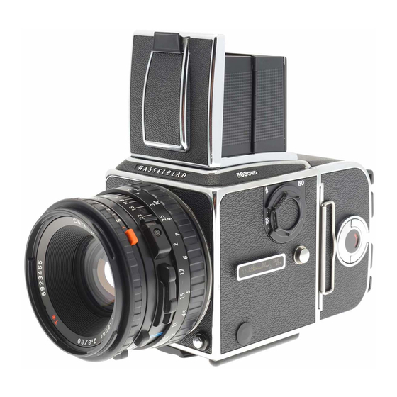
Hasselblad 503CW Service Manual
Camera body
Hide thumbs
Also See for 503CW:
- User manual (92 pages) ,
- Instruction manual (39 pages) ,
- User manual (86 pages)
Table of Contents
Advertisement
COPYRIGHT © 1996 ANDERS ENGSTRÖM
ANDERS ENGSTRÖM, ILLUSTRATÖR
Östra vägen 46
430 91 HÖNÖ
tel/fax 031- 96 84 64
anders@aeillustr.se
Copyright © 1998 by Victor Hasselblad AB. All rights reserved. No parts of this material may be reproduced, stored
in retrieval system or transmitted, in any form or by any means, electronic, mechanical, photocopy, recording, or
otherwise, without the prior written permission of the Company.
Service Manual
Victor Hasselblad AB
Göteborg Sweden
503CWOMS.EPS
960807
October 1996
Advertisement
Chapters
Table of Contents

Related Manuals for Hasselblad 503CW


Summary of Contents for Hasselblad 503CW
- Page 1 Victor Hasselblad AB Göteborg Sweden Copyright © 1998 by Victor Hasselblad AB. All rights reserved. No parts of this material may be reproduced, stored in retrieval system or transmitted, in any form or by any means, electronic, mechanical, photocopy, recording, or...
-
Page 2: Table Of Contents
Contents list Camera body 503CW General Tools Disassembly Reassembly Adjustment, final assembly and calibration of the flash meter Sub-assembly: Front bayonet plate and auxiliary shutter with mirror Exploded view: Shell Exploded view: Gear housing Exploded view: Mechanism plate Exploded view: Auxiliary shutter and mirror assembly... - Page 3 10/99 Stray-light - 503CW, 501CM, 501C, 503CX/CXi and 500C/M 01/00 New CD-ROM - Version 1.2 08/00 Washer added in the gear box - 501CM and 503CW 09/00 New CD-ROM - Version 1.3 14/00 Discontinued parts - 500 series cameras 01/01...
- Page 4 Related Service Infos 503CW - 501C - 503CX/CXi - 500C/M - 501CM 04/01 New CD-ROM - Version 2.0 Revision 4 January 2001...
- Page 5 64 - 4000. Tripod coupling: 1/4 in and 3/8 in socket threads and base plate for quick coupling attachments. Lens mount: Hasselblad bayonet mount for CF and C lenses. Hasselblad Acute-Matte D* focusing screen. Focusing screen: Sales code No. 42204. External 91L x 114W x 110H (3 9/16 x 4 1/2 x 4 11/32 in).
- Page 6 COPYRIGHT © 1996 ANDERS ENGSTRÖM Camera release sequence Camera body 503CW 503DGRM1 ANDERS ENGSTRÖM, ILLUSTRATÖR 961018 Östra vägen 46 430 91 HÖNÖ tel/fax 031- 96 84 64 anders@aeillustr.se Release sequence 360° position Pre- Variable released timing position interval 319° Mirror...
-
Page 7: Tools
Tools Camera body 503CW Tool No. Description Used for V-2200 Bender Signal arm adjustment V-2201 Bender Mirror arm adjustment V-2202 Bender S-arm adjustment V-2203 Bender Release arm adjustment (aux. shutter) V-2205 Bender Supporting tool when using V-2201 V-2206 Winding knob... - Page 8 Tools Camera body 503CW Tool No. Description Used for V-5423 Riveting jig Replacement of aux. shutter flaps V-5942 Exp. gauge Release mechanism adjustment 902474 Test box ELX/CX Calibration of the TTL flash meter 902658 Key angle gauge Adjustment of the front key angle...
-
Page 9: Disassembly
Camera body 503CW Disassembly Camera shell Remove the lens, film magazine, view finder, focusing screen and winding knob. Remove the screw (830060), coupling (22767) and washer (22799). Remove the leather (13374), shim (22473), screw (822701) and ISO selector knob (22495). - Page 10 Camera body 503CW Disassembly Circuit board (22575) *22882 CAUTION! When handling the circuit board a grounded bench mat and a wrist strap must be used to prevent ESD damage. Lift the chassis connector out of the hole in which it is seated in the left hand wall.
- Page 11 Camera body 503CW Disassembly Focusing screen frame (22812) Remove the two remaining screws (820015) holding the focusing screen frame to the right hand wall and lift the frame off. Right hand wall (21095-1) Remove (or cut) the foam plastic pad (22582) to get access to the three screws (820014).
- Page 12 Camera body 503CW Disassembly Remove the lower (13101) and the upper (13100) connecting rods and dismantle the remaining parts on the mechanism in the following order. Fig. 8. 1. Screws (820016) 2 pcs 2. Bearing bracket (13171) and nut (13116) 3.
-
Page 13: Reassembly
Camera body 503CW Reassembly The lubricants mentioned in the text are: Grease = Isoflex Topas L32 Oil = Isoflex PDP 48 Gear housing (30324) Lubricate carefully the washer (810840) with oil. Lubricate with grease and fit (incl. the above mentioned washer) the ratchet wheel (20924) into the front section of the gear housing (30304). - Page 14 Camera body 503CW Reassembly Mount the gear housing (30324) to the mechanism 20912 816802 810404 plate. 817112 On the reverse side of the mechanism plate lubricate the hub with grease and fit the shutter stop bar (20912) spring (816802), washer (810404) and clip (817112).
-
Page 15: Fig. 17
Camera body 503CW Reassembly Fitting the mechanism plate to the right hand wall On the mechanism plate fit the upper and lower connecting rods to the pins on the gear wheels. (13100) for the upper shutter and (13101) for the lower shutter. - Page 16 Camera body 503CW Reassembly Fit the stop lever (13355) and spring (816752) to the 821631 13108 814827 pre-greased hub. Secure with the clip (817119). Lubricate the hub (13108) with grease and place a shim onto it. This shim can be in several thicknesses for adjustment as follows: 0.10;...
- Page 17 Camera body 503CW Reassembly Rear plate (30300) Fitting the rear plate Fig. 23 and 24. Lubricate the shutter driving arm’s shaft hub and the mirror’s moving peg with grease. Connect the arm and the connecting rods and fix the rear plate into the chassis.
- Page 18 Camera body 503CW Reassembly Front plate (30777) Fitting the front bayonet plate to the camera body Tension the drive spring by turning the outer gear wheel clockwise four turns. The front key will be positioned at the red index dot.
-
Page 19: Gear Wheel
Camera body 503CW Adjustment The lubricants mentioned in the text are: Grease = Isoflex Topas L32 Oil = Isoflex PDP 48 Install the winding knob V-2206 and tension the 20919 V-2206 auxiliary shutter spring (30384) by releasing the pawl (20919). Turn the knob clockwise and tension the spring two turns at this time. - Page 20 Camera body 503CW Adjustment Focal length The camera body’s focal length is inspected and adjusted by using tool V-2229. The focal length is 71.40 mm ± 0.03 mm. "B" Zero the dial indicator by placing it on surface ”A”. Mount the front plate ”B” into the front bayonet of the camera.
- Page 21 Camera body 503CW Adjustment Adjustment No. 1 (Overtravel) With the film winding mechanism tensioned, check the V-2206 angle 15-16 with the bayonet plate tool 904644 pushed 904644 hard against the stop arm (13355). Measure the angle with a spring tension of 300 gm/cm. Adjust by altering the position of the bearing bracket (13171).
- Page 22 Camera body 503CW Adjustment Adjustment of the release mechanism Check that the release bar (30375) is free from the signal arm pawl. Adjust by carefully bending the forward part of the signal arm. Use tool V-2200. Minimum free play: 0.2 mm.
- Page 23 Camera body 503CW Adjustment The push rod (22369) is adjusted so that it is set 0.15 mm below the release bar (30375) forward angle setting. Check by using the tool V-5942. 30375 Adjust by gently bending (22369). Fig. 37. 22369 0.15 mm...
- Page 24 Camera body 503CW Adjustment Adjustment of the release sequence Make sure the winding knob V-2206 and the bayonet plate tool 904644 are installed. Release the camera and keep it released by holding the release bar and push rod back. Move the release bar and push rod to the front slowly V-2206 and observe the closing sequence.
- Page 25 Camera body 503CW Adjustment Operate the winding knob V-2206 to cock the shutter. Check that the bayonet plate tool 904644 is blocked by the stop lever (22769) when the camera is completely 904644 V-2206 cocked. Adjust by bending the front of the lever. The lever...
- Page 26 Camera body 503CW Adjustment Fitting the Circuit board (22575) *22882 CAUTION! When handling the circuit board a grounded bench mat and a wrist strap must be used to prevent ESD damage. Put the insulating plate (22746) in position and place the circuit board on top of it.
- Page 27 Camera body 503CW Adjustment Adjust the lower rear plate/shell alignment and tighten the two rear screws (829755)and seal with loctite. Fit and tighten the two front screws (820781). Check the upper edge alignment of rear plate and shell. Adjust, if necessary, the two screws (825760) which are accessible behind the leathers mounted on the shell.
- Page 28 5:10 Camera body 503CW Adjustment Check the mirror 45 angle using the sighting tube which fits in the holder on the gauge. Tighten the locking screw. Shine a light source towards the oval cut-out in the upper part of the tube so that the white ring of the ocular is illuminated.
- Page 29 5:11 Camera body 503CW Adjustment Check the camera functions. Check that the auxiliary shutter is clear of the internal covers. Check the release sequence using a micrometer V-2354. Mount the micrometer in the exposure button’s cable release socket. Carefully screw in the micrometer’s screw until the camera releases.
- Page 30 Control/calibration should be carried out each time the camera has been in for repair. The tolerance for the flash meter is ±0.3 EV at all settings. If the Hasselblad Service System 970600 is used, follow the step by step instruction in the STS user manual.
- Page 31 5:13 Camera body 503CW Adjustment Calibration On pressing the MEASURE button one of the three LED´s will light. The variable resistor in the camera (access behind the leather beside the ISO dial) should be turned so that the green LED lights when the MEASURE button is pressed again.
-
Page 32: Screw (822605)
Camera body 503CW Front bayonet plate Front plate reassembly Fit the four bayonet tongues (103439) and secure with eight screws (820425). Fit the release button return spring (21096) with one screw (820015). Behind the front plate glue the two sponge seals (13212) and (13213) as well as the foils (22829) and (22832) into place. - Page 33 Camera body 503CW Front bayonet plate The hole for the locating pin (812202) is bored with 1.15 mm drill. Use tool V-2211 for driving in the pin. Drive the pin in until the face of the tool touches the front bayonet plate. When a new front plate is installed...
-
Page 34: Fig. 58
Camera body 503CW Auxillary shutter & Mirror Exchanging the mirror (22775) Release the camera. Inside the mirror box, remove the clip "A" and disengage the arm (22781) from the mirror frame. 810649 Remove the washer (810649) located behind the arm 22781 and the frame. -
Page 35: Fig. 61
Camera body 503CW Auxillary shutter & Mirror Remount the mirror frame and the upper shutter flap by holding the frame in position and aligning the upper shutter flap to the bearing holes. Push in both bearing hubs and centralise the mirror and Shim washers shutter flap side movement by using shim washers. - Page 36 Camera body 503CW COPYRIGHT © 1997 ANDERS ENGSTRÖM BOD50301.EPS ANDERS ENGSTRÖM, ILLUSTRATÖR 970512 Östra vägen 46 430 91 HÖNÖ tel/fax 031- 96 84 64 anders@aeillustr.se Revision 1 May 1997...
- Page 37 Camera body 503CW Description Spare Remark Part No. 40 393 Shell, complete (chrome) Part No. 40394 (black) 30 762 Support, right 105 872 Tape 30 760 Support, left 105 870 Tape 831 502 Rivet 40 387 Support 103 504 Leather...
- Page 38 Camera body 503CW C O P Y R I G H T B O D 5 0 3 0 2 . E P A N D E R S E N G S T R 0 0 0 5 0...
- Page 39 Camera body 503CW Description Spare Remark Part No. 30 324 Gear housing Complete 830 060 Screw 820 415 Screw 22 767 Coupling 22 799 Washer Alternatively 2 pcs 820 020 Screw 816 507 Spring 13 170 Adjustable pawl 820 019...
- Page 40 Camera body 503CW COPYRIGHT © 1997 ANDERS ENGSTRÖM BOD50303.EPS ANDERS ENGSTRÖM, ILLUSTRATÖR 970515 Östra vägen 46 430 91 HÖNÖ tel/fax 031- 96 84 64 anders@aeillustr.se Revision 1 May 1997...
- Page 41 Camera body 503CW Description Spare Remark Part No. 822 605 Screw 810 836 Washer 22 287 Damping ring 14 280 14 278 O-ring 30 384 Spring 22 699 Gear 810 953 Washer (0.3 mm) 820 015 Screw 823 015 Screw...
- Page 42 Camera body 503CW BOD50304.EPS COPYRIGHT © 1999 ANDERS ENGSTRÖM 990906 ANDERS ENGSTRÖM, ILLUSTRATÖR Östra vägen 46 430 91 HÖNÖ tel/fax 031- 96 84 64 anders@aeillustr.se Revision 1 September 1999...
- Page 43 Camera body 503CW Description Spare Remark Part No. 30 300 Rear plate, complete State serial No. 40 237 Rear plate State serial No. 816 805 Spring 816 804 Spring 13 125 Light trap 821 203 Screw 13 397 Foam plastic strip 810503 Washer (0.10 mm)
- Page 44 Camera body 503CW BOD50305.EPS COPYRIGHT © 1999 ANDERS ENGSTRÖM 990906 ANDERS ENGSTRÖM, ILLUSTRATÖR Östra vägen 46 430 91 HÖNÖ tel/fax 031- 96 84 64 anders@aeillustr.se Revision 2 September 1999...
- Page 45 Camera body 503CW Description Spare Remark Part No. 30 777 Front bayonet plate Complete 40 403 Front bayonet plate 30 383 Front gear 30 386 Governor 820 014 Screw 821 009 Screw 820 018 Screw 812 202 823 440 Screw...
- Page 46 Camera body 503CW BOD50306.EPS COPYRIGHT © 1999 ANDERS ENGSTRÖM 990906 ANDERS ENGSTRÖM, ILLUSTRATÖR Östra vägen 46 430 91 HÖNÖ tel/fax 031- 96 84 64 anders@aeillustr.se Revision 1 September 1999...
- Page 47 Camera body 503CW Description Spare Remark Part No. 30 686 Bottom plate 30 375 Release bar 814 512 Spring 22 717 Signal arm 814 603 Spring 21095 Inner wall, right 817 119 Clip 820 014 Screw 13 356 Mirror catch...
- Page 48 Camera body 503CW BOD50307.EPS 960806 COPYRIGHT © 1996 ANDERS ENGSTRÖM ANDERS ENGSTRÖM, ILLUSTRATÖR Östra vägen 46 430 91 HÖNÖ tel/fax 031- 96 84 64 anders@aeillustr.se Revision 0 October 1996...
- Page 49 Camera body 503CW Description Spare Remark Part No. 22 577 Clip 22576 Bracket 823 335 Screw 22 470 Socket cap 22 575 PC board See below 22 746 Insulating plate 820 011 Screw 12 453 Cable holder 22 453 Attachment...
- Page 50 BOD50308.EPS Camera body 503CW COPYRIGHT © 1996 ANDERS ENGSTRÖM 960710 ANDERS ENGSTRÖM, ILLUSTRATÖR Östra vägen 46 430 91 HÖNÖ tel/fax 031- 96 84 64 anders@aeillustr.se Revision 0 October 1996...
- Page 51 Camera body 503CW Description Spare Remark Part No. 103 517 Leather 815 904 Spring 815 707 Spring 103 516 Washer 103 113 Crank bayonet 107 409 Crank support 829 540 Screw 103 151 Crank arm 103 514 Slide 812 301...
-
Page 52: Camera Body 501C
15:1 Camera body 501C COPYRIGHT © 1997 ANDERS ENGSTRÖM BOD50101.EPS ANDERS ENGSTRÖM, ILLUSTRATÖR 970515 Östra vägen 46 430 91 HÖNÖ tel/fax 031- 96 84 64 anders@aeillustr.se Revision 1 May 1997... - Page 53 15:1 Camera body 501C Description Spare Remark Part No. 40 384 Shell, complete 22 782 Name plate 103 592 Leather 103 529 Accessory rail Spare parts not listed are the same as for 503CW Revision 0 October 1996...
- Page 54 15:2 Camera body 501C COPYRIGHT © 1997 ANDERS ENGSTRÖM 501CM02.EPS ANDERS ENGSTRÖM, ILLUSTRATÖR 970514 Östra vägen 46 430 91 HÖNÖ tel/fax 031- 96 84 64 anders@aeillustr.se Revision 1 May 1997...
- Page 55 22 799 Washer Alternatively none or 1 pc 412 401 Spacer 830 061 Screw 412 103 Coupling New type of winding crank from camera serial No.17EU10379 Spare parts not listed are the same as for 503CW Revision 1 May 1997...
- Page 56 15:3 BOD50102.EPS COPYRIGHT © 1996 ANDERS ENGSTRÖM 961022 ANDERS ENGSTRÖM, ILLUSTRATÖR Camera body 501C Östra vägen 46 430 91 HÖNÖ tel/fax 031- 96 84 64 anders@aeillustr.se Revision 1 May 1997...
- Page 57 30 519 Rear plate, complete State serial No. 20 958 Mirror assembly 20 901 Mirror protection 13 141 Foam plastic pad 20 854 Mirror 20 956 Frame Spare parts not listed are the same as for 503CW Revision 1 May 1997...
- Page 58 15:4 Camera body 501C BOD50103.EPS COPYRIGHT ' 2000 ANDERS ENGSTR M 000530 ANDERS ENGSTR M, ILLUSTRAT R stra v gen 46 430 91 H N tel/fax 031- 96 84 64 anders@aeillustr.se Revision 3 May 2000...
- Page 59 13 351 Foam plastic strip 13 211 Foam plastic strip 22 429 Foam plastic strip 22 873 Reflection protector 22 892 Cover Incl. reflection protector 22 873 Spare parts not listed are the same as for 503CW Revision 3 May 2000...
- Page 60 15:5 BOD50104.EPS COPYRIGHT © 1997 ANDERS ENGSTRÖM 970512 ANDERS ENGSTRÖM, ILLUSTRATÖR Camera body 501C Östra vägen 46 430 91 HÖNÖ tel/fax 031- 96 84 64 anders@aeillustr.se Revision 1 May 1997...
- Page 61 15:5 Camera body 501C Description Spare Remark Part No. 22 750 Coupling 22 751 Crank support Spare parts not listed are the same as for 503CW Revision 1 May 1997...
-
Page 62: Camera Body 503Cxi
16:1 COPYRIGHT © 1996 ANDERS ENGSTRÖM Camera body 503CXi 503CXi01.EPS ANDERS ENGSTRÖM, ILLUSTRATÖR Östra vägen 46 430 91 HÖNÖ 961029 tel/fax 031- 96 84 64 anders@aeillustr.se Revision 0 October 1996... - Page 63 16:1 Camera body 503CXi Description Spare Remark Part No. 22 771 Name plate Spare parts not listed are the same as for 503CW Revision 0 October 1996...
- Page 64 16:2 BOD50102.EPS COPYRIGHT © 1996 ANDERS ENGSTRÖM 961022 ANDERS ENGSTRÖM, ILLUSTRATÖR Camera body 503CXi Östra vägen 46 430 91 HÖNÖ tel/fax 031- 96 84 64 anders@aeillustr.se Revision 0 October 1996...
- Page 65 30 519 Rear plate, complete State serial No. 20 958 Mirror assembly 20 901 Mirror protection 13 141 Foam plastic pad 20 854 Mirror 20 956 Frame Spare parts not listed are the same as for 503CW Revision 0 October 1996...
- Page 66 16:3 Camera body 503CXi 503CXi03.EPS COPYRIGHT ' 2000 ANDERS ENGSTR M ANDERS ENGSTR M, ILLUSTRAT R stra v gen 46 000530 430 91 H N tel/fax 031- 96 84 64 anders@aeillustr.se Revision 2 May 2000...
- Page 67 13 351 Foam plastic strip 13 211 Foam plastic strip 22 429 Foam plastic strip 22 873 Reflection protector 22 876 Cover Incl. reflection protector 22 873 Spare parts not listed are the same as for 503CW Revision 2 May 2000...
-
Page 68: Camera Body 503Cx
17:1 Camera body 503CX COPYRIGHT © 1996 ANDERS ENGSTRÖM 503CX01.EPS ANDERS ENGSTRÖM, ILLUSTRATÖR Östra vägen 46 430 91 HÖNÖ 961029 tel/fax 031- 96 84 64 anders@aeillustr.se Revision 0 October 1996... - Page 69 Name plate 103 846 Tripod socket 1/4" Standard 402 347 Tripod socket 3/8" Optional 824 701 Screw 823 735 Screw 823 781 Screw 103 349 Slide Spare parts not listed are the same as for 503CW Revision 0 October 1996...
- Page 70 17:2 Camera body 503CX COPYRIGHT © 1996 ANDERS ENGSTRÖM 503CX02.EPS ANDERS ENGSTRÖM, ILLUSTRATÖR 961025 Östra vägen 46 430 91 HÖNÖ tel/fax 031- 96 84 64 anders@aeillustr.se Revision 0 October 1996...
- Page 71 Description Spare Remark Part No. 821 806 Screw 13 436 Locking washer 13 163 Bayonet plate 13 360 Shim, 0.2 mm For adjustment 13360-01, 0.4 mm Spare parts not listed are the same as for 503CW Revision 0 October 1996...
- Page 72 17:3 BOD50102.EPS COPYRIGHT © 1996 ANDERS ENGSTRÖM 961022 ANDERS ENGSTRÖM, ILLUSTRATÖR Camera body 503CX Östra vägen 46 430 91 HÖNÖ tel/fax 031- 96 84 64 anders@aeillustr.se Revision 0 October 1996...
- Page 73 30 519 Rear plate, complete State serial No. 20 958 Mirror assembly 20 901 Mirror protection 13 141 Foam plastic pad 20 854 Mirror 20 956 Frame Spare parts not listed are the same as for 503CW Revision 0 October 1996...
- Page 74 17:4 Camera body 503CX 503CX03.EPS COPYRIGHT ' 2000 ANDERS ENGSTR M ANDERS ENGSTR M, ILLUSTRAT R stra v gen 46 000530 430 91 H N tel/fax 031- 96 84 64 anders@aeillustr.se Revision 2 May 2000...
- Page 75 22 429 Foam plastic strip 22 873 Reflection protector 22 876 Cover Incl. reflection protector 22 873 13 220 Signal arm Mounted on the right inner wall Spare parts not listed are the same as for 503CW Revision 2 May 2000...
- Page 76 17:5 Camera body 503CX 503CX04.EPS COPYRIGHT © 1994 ANDERS ENGSTRÖM 961031 ANDERS ENGSTRÖM, ILLUSTRATÖR Östra vägen 46 430 91 HÖNÖ TEL/FAX 031-96 84 64 Mounted on the mechanism plate Revision 0 October 1996...
- Page 77 Bayonet plate 824 602 Screw 402 321 Crank support 815 856 Spring 402 413 Button 14 221 Leather 13 355 Stop lever Mounted on the mechanism plate Spare parts not listed are the same as for 503CW Revision 0 October 1996...
-
Page 78: Camera Body 500C/M (Classic)
18:1 Camera body 500C/M (Classic) 500CM01.EPS COPYRIGHT © 1996 ANDERS ENGSTRÖM ANDERS ENGSTRÖM, ILLUSTRATÖR 961029 Östra vägen 46 430 91 HÖNÖ tel/fax 031- 96 84 64 anders@aeillustr.se Revision 0 October 1996... - Page 79 Name plate 402 347 Tripod socket 3/8" Standard 103 846 Tripod socket 1/4" Optional 824 701 Screw 823 735 Screw 823 781 Screw 103 349 Slide Spare parts not listed are the same as for 503CW Revision 0 October 1996...
- Page 80 18:2 Camera body 500C/M (Classic) COPYRIGHT © 1996 ANDERS ENGSTRÖM 503CX02.EPS ANDERS ENGSTRÖM, ILLUSTRATÖR 961025 Östra vägen 46 430 91 HÖNÖ tel/fax 031- 96 84 64 anders@aeillustr.se Revision 0 October 1996...
- Page 81 Description Spare Remark Part No. 821 806 Screw 13 436 Locking washer 13 163 Bayonet plate 13 360 Shim, 0.2 mm For adjustment 13360-01, 0.4 mm Spare parts not listed are the same as for 503CW Revision 0 October 1996...
- Page 82 18:3 BOD50102.EPS COPYRIGHT © 1996 ANDERS ENGSTRÖM 961022 ANDERS ENGSTRÖM, ILLUSTRATÖR Camera body 500C/M (Classic) Östra vägen 46 430 91 HÖNÖ tel/fax 031- 96 84 64 anders@aeillustr.se Revision 0 October 1996...
- Page 83 30 519 Rear plate, complete State serial No. 20 958 Mirror assembly 20 901 Mirror protection 13 141 Foam plastic pad 20 854 Mirror 20 956 Frame Spare parts not listed are the same as for 503CW Revision 0 October 1996...
- Page 84 18:4 Camera body 500C/M (Classic) 500CM02.EPS COPYRIGHT ' 2000 ANDERS ENGSTR M 000530 ANDERS ENGSTR M, ILLUSTRAT R stra v gen 46 430 91 H N tel/fax 031- 96 84 64 anders@aeillustr.se Revision 2 May 2000...
- Page 85 22 429 Foam plastic strip 22 873 Reflection protector 22 892 Cover Incl. reflection protector 22 873 13 220 Signal arm Mounted on the right inner wall Spare parts not listed are the same as for 503CW Revision 2 May 2000...
- Page 86 18:5 Camera body 500C/M (Classic) 503CX04.EPS COPYRIGHT © 1994 ANDERS ENGSTRÖM 961031 ANDERS ENGSTRÖM, ILLUSTRATÖR Östra vägen 46 430 91 HÖNÖ TEL/FAX 031-96 84 64 Mounted on the mechanism plate Revision 0 October 1996...
- Page 87 Bayonet plate 824 602 Screw 402 321 Crank support 815 856 Spring 402 413 Button 14 221 Leather 13 355 Stop lever Mounted on the mechanism plate Spare parts not listed are the same as for 503CW Revision 1 January 2001...
-
Page 88: Camera Body 501Cm
19:1 Camera body 501CM COPYRIGHT © 1997 ANDERS ENGSTRÖM 501CM01.EPS ANDERS ENGSTRÖM, ILLUSTRATÖR 970513 Östra vägen 46 430 91 HÖNÖ tel/fax 031- 96 84 64 anders@aeillustr.se Revision 0 May 1997... - Page 89 Camera body 501CM Description Spare Remark Part No. 40 407 Shell, complete (Chrome) Part No. 40408 (black) 22 862 Name plate 103 592 Leather 103 529 Accessory rail Spare parts not listed are the same as for 503CW Revision 1 October 1997...
- Page 90 19:2 Camera body 501CM C O P Y R I G H T 5 0 1 C M 0 2 . E P A N D E R S E N G S T R 0 0 0 5 0 9 430 91 H tel/fax 031- a n d e r s @ a e i l l u s t r .
- Page 91 Description Spare Remark Part No. 13 355 Stop lever 22 799 Washer Alternatively none or 1 pc 412 401 Spacer 830 061 Screw 412 103 Coupling Spare parts not listed are the same as for 503CW Revision 0 May 1997...
- Page 92 19:3 501CM03.EPS COPYRIGHT © 1999 ANDERS ENGSTRÖM 990906 ANDERS ENGSTRÖM, ILLUSTRATÖR Camera body 501CM Östra vägen 46 430 91 HÖNÖ tel/fax 031- 96 84 64 anders@aeillustr.se Revision 1 September 1999...
- Page 93 Camera body 501CM Description Spare Remark Part No. 22 865 Light shield 22 806 Frame, complete 22 873 Reflection protector 22 892 Cover Incl. reflection protector 22 873 Spare parts not listed are the same as for 503CW Revision 1 September 1999...
Need help?
Do you have a question about the 503CW and is the answer not in the manual?
Questions and answers