
Related Manuals for Horus DOMUS

Summary of Contents for Horus DOMUS
- Page 1 Non è stata trovata alcuna voce d'indice. STUFA A PELLET DOMUS MANUALE DI INSTALLAZIONE USO E MANUTENZIONE MOD. DOMUS (IT)
- Page 2 Sommario INFORMAZIONI GENERALI ........................4 SIMBOLOGIA UTILIZZATA ........................4 SCOPO E CONTENUTO DEL MANUALE ....................4 DESTINAZIONE D’USO ........................... 4 GENERALITA’ ............................4 NORMATIVE DI RIFERIMENTO ......................4 GARANZIA ............................. 4 RESPONSABILITA’ DEL COSTRUTTORE ....................4 CONSEGNA E CONTROLLO DELLA STUFA ..................... 5 SICUREZZA .............................
- Page 3 MENU 02 – SET CRONO ........................15 SOTTOMENU 04-01 ABILITA CRONO ....................15 SOTTOMENU 04-02 PROGRAMMAZIONE GIORNALIERA ..............16 SOTTOMENU 04-03 PROGRAMMAZIONE SETTIMANALE ..............16 SOTTOMENU 04-04 PROGRAMMAZIONE WEEK-END ..............18 MENU 03 SCEGLI LINGUA ........................ 19 MENU 04 MODO STAND-BY ......................19 MENU 05 MODO CICALINO ......................
- Page 4 4) DESTINAZIONE D’USO Il presente prodotto modello DOMUS è una stufa alimentata con combustibile a pellet di legno per uso interno. Di seguito si riportano le indicazioni inerenti l’uso stesso del macchinari: Non aprire la porta durante il funzionamento della stufa.
- Page 5 Installazione non conforme Inosservanza parziale o totale delle istruzioni contenute nel presente manuale Installazione da parte di personale non qualificato e/o addestrato Uso non conforme delle direttive di sicurezza Modifiche e riparazioni non autorizzate dalla ditta costruttrice Utilizzo di ricambi non originali o non specifici per il modello di stufa Inosservanza manutentiva Eventi eccezionali 9) CONSEGNA E CONTROLLO DELLA STUFA...
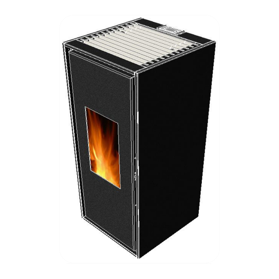
- Page 6 FIG.1...
- Page 7 13) CARATTERISTICHE TECNICHE 14) TIPI E DIMENSIONI DI COMBUSTIBILI RACCOMANDATI Utilizzare combustibile conforme ai requisiti richiesti dalla Norma A1/A2 secondo ISO 17225-2 (ex UNI EN 14961). Si consiglia l’utilizzo di pellet avente le caratteristiche di seguito riportate: Tipo di Pellet LEGNO VERGINE Diametro 6/8 mm...
- Page 8 TAB 2 Maniglia apertura porta Braciere\Crogiuolo Coperchio serbatoio pellet FIG. 2 16) INSTALLAZIONE Solamente il tecnico qualificato ed autorizzato deve, nel pieno rispetto delle normative vigenti e delle istruzioni di montaggio, eseguire l’installazione, l’allaccio e la verifica del buon funzionamento della stufa. FONTANA FORNI SRL, nel caso di installazione difforme da quella consigliata, declina ogni responsabilità...
- Page 9 FIG. 3 Uscita scarico fumi posteriore Ø80mm Ingresso aria comburente Ø35mm Rear fume exhaustion outlet Ø80mm Air fuel access Ø35mm 19) AVVERTENZE DI SICUREZZA PER L’ALLACCIAMENTO/ATTIVAZIONE DELLA STUFA Il collegamento elettrico della stufa alla rete elettrica viene effettuato tramite un cavo a norma in dotazione; l’installatore è responsabile del corretto collegamento elettrico, il quale deve avvenire conformemente alle norme di sicurezza.
- Page 10 In alternativa si consiglia l’impiego di tubo industriale coibentato che può essere usato anche all’esterno per evitare la condensa. ATTENZIONE È necessario utilizzare sempre tubi e raccordi con adeguate guarnizioni che garantiscano l’ermeticità. Tutti i tratti del condotto fumario devono essere ispezionabili e removibili per rendere possibile la periodica pulizia interna. ATTENZIONE Tutti i cambi di direzione a 90 gradi del canale di scarico fumi devono essere possibilmente realizzati con gli appositi raccordi a “T”...
- Page 11 23) COLLEGAMENTO A CANNA FUMARIA La canna fumaria deve avere dimensioni interne non superiori a cm 20 x 20 o diametro non superiore a 20 cm; nel caso di dimensioni superiori o cattive condizioni della canna fumaria (es. crepe, scarso isolamento, ecc.) è consigliato inserire nella canna fumaria un tubo in acciaio inox del diametro adeguato per tutta la lunghezza, fino alla cima.
- Page 12 27) DISTANZA MINIMA DA MATERIALE INFIAMMABILE Distanza minima in aria posteriore da parete infiammabile P = 200mm Distanza minima in aria laterale da parete infiammabile L = 400mm Distanza minima in aria da pavimento infiammabile Spessore materiale isolante sul pavimento ...
- Page 13 29) MANUTENZIONE ORDINARIA IMPORTANTE: è necessario ad ogni riaccensione pulire il braciere (F), una volta ogni 2-3 giorni pulire il cassetto cenere (I) ed il supporto braciere (H). Si consiglia una volta al mese di smontare anche il parafiamma (L) e il tappo ispezione fumi, situato dietro il cassetto cenere (Z), ripulendo con aspirapolvere adeguato.
- Page 14 30) CONSOLE La console visualizza le informazioni sullo stato di funzionamento della stufa. Accedendo al menù è possibile ottenere vari tipi di visualizzazione ed effettuare le impostazioni disponibili a seconda del livello di accesso. Dipendendo dalla modalità operativa, le visualizzazioni possono assumere differenti significati a seconda della posizione sul display. In figura esempio di condizioni di stufa spenta o accesa.
- Page 15 32) IL MENU Con pressione sul tasto P3 (MENU) si accede al menù. Questo è suddiviso in varie voci e livelli che permettono di accedere alle impostazioni e alla programmazione della scheda. Le voci di menu che consentono di accedere alla programmazione tecnica sono protette da chiave di accesso, solo il tecnico abilitato potrà...
- Page 16 37) SOTTOMENU 02-02 PROGRAMMAZIONE GIORNALIERA Permette di abilitare, disabilitare e impostare le funzioni di cronotermostato giornaliero. È possibile impostare due fasce di funzionamento, date da 2 accensioni e da 2 spegnimenti, si può attivare e disattivare la funzione giornaliera lasciando in memoria la programmazione impostata, il progresso della programmazione nel grafico figura seguente. Inizio Premere P5 Premere P3...
- Page 17 Programma 1 Selezione Significato Valori possibili Start Prog 1 Ora di attivazione Ora-OFF Stop prog 1 Ora di disattivazione Ora-OFF Lunedì prog 1 On/off Martedì prog 1 On/off Mercoledì prog 1 On/off Giorni di riferimento Giovedì prog 1 On/off Venerdì prog 1 On/off Sabato prog 1 On/off...
- Page 18 Programma 4 Selezione Significato Valori possibili Start Prog 4 Ora di attivazione Ora-OFF Stop prog 4 Ora di disattivazione Ora-OFF Lunedì prog 4 On/off Martedì prog 4 On/off Mercoledì prog 4 On/off Giorni di riferimento Giovedì prog 4 On/off Venerdì prog 4 On/off Sabato prog 4 On/off...
- Page 19 40) MENU 03 SCEGLI LINGUA Permette di selezionare la lingua di dialogo tra quelle disponibili. Di seguito la procedura per selezionare la lingua desiderata. Premere P3 Inizio Premere P3 Premere P2 1 volta 2 volte 1 volta P1 - P2 Premere P4 per scegliere la lingua per uscire...
- Page 20 44) MENU 07 STATO STUFA Visualizza lo stato istantaneo della stufa riportando lo stato dei vari dispositivi ad essa collegati. Sono disponibili diverse pagine visualizzate in successione Premere P3 Inizio Premere P3 Premere P2 1 volta 6 volte 1 volta Premere P4 per uscire 45) MENU 08 TARATURE TECNICO...
- Page 21 55) PULIZIA BRACIERE Durante la normale operatività nella modalità lavoro, a intervalli programmati nella parametria di funzionamento, viene attivata la modalità PULIZIA BRACIERE per la durata stabilita. In questa fase si noterà un incremento della rotazione dell’aspiratore fumi e una diminuizione della discesa di pellet, questo per permettere la completa combustione e al sollevamento e estrazione delle ceneri all’interno del bracere.
- Page 22 ALLARME SPEGNIMENTO DURANTE LA FASE DI LAVORO Se durante la fase di lavoro la fiamma si spegne e la temperatura fumi scende al di sotto della soglia minima di lavoro si attiva l’allarme. Durante la condizione di allarme la stufa esegue la procedura di spegnimento. (La causa dello spegnimento possono essere: pellet esaurito all’interno del serbatoio, motore coclea bloccato da corpi estranei.) ALLARME PRESSOSTATO DI SICUREZZA Nell’eventualità...
- Page 23 energetico (DOPO AVER DISINSERITO LA SPINA DALLA (blackout) Spina di alimentazione PRESA DI ALIMENTAZIONE) il buon collegata in modo non funzionamento dell’interruttore, gli innesti e i corretto serraggi dei morsetti La stufa dichiara Sonde di controllo temperatura Contattare il servizio tecnico “Sonda fumi deteriorata temperatura fumi”...
- Page 24 64) AVVERTENZE FONDAMENTALI ATTENZIONE Spegnere e lasciare raffreddare l’apparecchio a temperatura ambiente prima di procedere alla manutenzione. Attendere almeno 1 ora dopo lo spegnimento dell’apparecchio. ATTENZIONE Utilizzare sempre guanti anticalore per evitare possibili ustioni alla pelle. ATTENZIONE Disattivare l’interruttore posteriore spostandolo su “0” (Figura 1). Togliere la spina dalla presa di corrente. ATTENZIONE Non scollegare l’apparecchio dalla presa di corrente o disattivare l’interruttore posteriore spostandolo su “0”...
- Page 25 68) CONDIZIONI DI GARANZIA E RICHIESTA INTERVENTO La garanzia dell’apparecchio ha durata di anni due, così come previsto dalla Direttiva Europea 1999/44/CE sulla vendita dei beni di consumo. Il periodo è conteggiato a partire dalla data riportata sullo scontrino fiscale d’acquisto o sulla fattura o altro documento fiscale che comprovi l’avvenuto acquisto con data certa.
- Page 26 FONTANA FORNI SRL 69) CERTIFICATO DI GARANZIA MODELLO MATRICOLA DATI DEL RIVENDITORE: Timbro …………………………………………………………………………………………………. DATI D’ACQUISTO ………………………………………………………………………………………………… E mail ………………………………… ACQUIRENTE Firma …………………………………. Nome ..........................Via ..........................Città …................Cap.......... Nazione..........E mail............... Tel: ............Cell............. IMPORTANTE: FONTANA FORNI SRL Per la validità...
- Page 27 INFORMAZIONI AGLI UTENTI Ai sensi del decreto legislativo 49/2014” Attuazione delle Direttive 2002/95/CE,2002/96/CE e 2003/108/CE, relative alla riduzione dell’uso di sostanze pericolose nelle apparecchiature elettriche ed elettroniche, nonché allo smaltimento dei rifiuti”. Il simbolo del cassonetto barrato riportato sull’apparecchiatura o sulla confezione indica che il prodotto alla fine della propria vita utile deve essere smaltito in modo idoneo.
- Page 28 NOTE _____________________________________________________________________________________ _____________________________________________________________________________________ _____________________________________________________________________________________ _____________________________________________________________________________________ _____________________________________________________________________________________ _____________________________________________________________________________________ _____________________________________________________________________________________ _____________________________________________________________________________________ _____________________________________________________________________________________ _____________________________________________________________________________________ _____________________________________________________________________________________ _____________________________________________________________________________________ _____________________________________________________________________________________ _____________________________________________________________________________________ _____________________________________________________________________________________ _____________________________________________________________________________________ _____________________________________________________________________________________ _____________________________________________________________________________________ _____________________________________________________________________________________ _____________________________________________________________________________________ _____________________________________________________________________________________ _____________________________________________________________________________________ _____________________________________________________________________________________ _____________________________________________________________________________________ _____________________________________________________________________________________ _____________________________________________________________________________________ _____________________________________________________________________________________ _____________________________________________________________________________________ _____________________________________________________________________________________ _____________________________________________________________________________________ _____________________________________________________________________________________ _____________________________________________________________________________________ _____________________________________________________________________________________ _____________________________________________________________________________________ _____________________________________________________________________________________ _____________________________________________________________________________________ _____________________________________________________________________________________ _____________________________________________________________________________________ _____________________________________________________________________________________ _____________________________________________________________________________________ _____________________________________________________________________________________ _____________________________________________________________________________________...
- Page 29 FONTANA FORNI SRL Via G. Di Vittorio, 6 61047 San Lorenzo in Campo (PU) Italy Tel. +39.0721.776697 - Fax +39.0721.735370...
- Page 30 PELLET STOVE: DOMUS INSTALLATION AND MAINTENANCE MANUAL MOD. DOMUS (EN)
- Page 31 1. GENERAL NOTICE ............................32 2. SYMBOLS ................................ 32 3. PURPOSE AND CONTENTS OF THIS MANUAL ....................32 4. INTENDED USE ............................... 32 5. GENERAL INFORMATION ..........................32 6. SAFETY STANDARDS ............................32 7. WARRANTY ..............................32 8. MANUFACTURER'S LIABILITY ......................... 33 SAFETY INFORMATION ..........................
- Page 32 1. GENERAL NOTICE This manual is intended for owners, installers, users and maintenance personnel of the DOMUS series stoves and is an integral part of the product. FONTANA FORNI SRL heating appliances are built and tested in accordance with the safety requirements specified by the European directives.
- Page 33 8. MANUFACTURER'S LIABILITY By providing this manual, FONTANA FORNI SRL, declined all liability, both civil and criminal, direct or indirect, deriving from: Non compliant installation Partial or total failure to follow the instructions provided in this manual Installation by unqualified or untrained personnel Use not in compliance with safety directives Modifications and repairs on the stove which are not authorised by the manufacturer Use of spare parts which are not original or not specific for the model of the stove...
- Page 34 STOVE DESCRIPTION The pellet stove was built with materials conceived and designed especially for this purpose. The stove main parts and controls are described in figure 1 and in table 1. TAB. 1a Combustion chamber door Pellet tank lid Combustion chamber door handle Fume exhaustion outelt Air louvers Inlet for power supply 220 volts-50hz...
- Page 35 TECHNICAL INFORMATION 12. FUEL TYPE AND QUANTITY Use fuel compliant with A1/A2 secondo ISO 17225-2 (ex UNI EN 14785/2006). Pellets with the following features are recommended: Type of pellet: VIRGIN WOOD Diameter 6\8 mm Average length 15/20 mm Moisture Heating power Max 4.500 Kcal/Kg Power/Weight Max 5,3 Kw/Kg...
- Page 36 13. VISUAL MATCH OF THE STOVE The technician must visually and manually match the stove parts portrayed in figure 2 and in table 2 with the product description. He/she will also check that the parts are compliant with current regulations and haven't been damaged whatsoever. For any doubts regarding FONTANA FORNI SRL damages to the device please contact TAB.
- Page 37 Put the stove on the floor in a place where it can be easily connected to the flue and to the exhausting and thermal system. Connect the flue checking that the fume exhaustion outlet, on the back or on the right side of the stove, is positioned correctly. (figure 3) Fig.
- Page 38 EXTERNAL AIR INTAKE AND CONNECTION TO THE FLUE Any connection between the stove and the flue must be protected for your children's safety. For your own safety and comfort, please make sure that the room has a suitable air scoop (UNI10683). For the good functioning of the stove, leave adequate clearance and air for the pellets to burn.To add an external air scoop make a hole on the external wall, close to the stove.
- Page 39 CONNECTION TO THE FLUE (Figura 8) For the best possible stove functioning, the connection to the flue exhaustion pipe or system must have a positive gradient of no less than 3% in horizontal pipes. The overall length shall not be more than 2 m whereas, in vertical pipes, between a “T” fitting and other fittings (change of directions) there must be a distance of minimum 1.5 m and maximum 3 m By using adequate tools, check that there is a flue draught of at least 12 PA.
- Page 40 MINIMUM DISTANCE FROM FLAMMABLE MATERIAL Minimum distance from flammable wall in rear air P = 200mm Minimum distance from flammable wall side air L = 400mm Minimum distance from flammable in air floor insulation thickness on the floor ...
- Page 41 ROUTINE MAINTENANCE IMPORTANT : clean the brazier every time you switch the stove on (Position F) once every 2-3 days have the ash pan (Position I) and the brazier support cleaned (Position L). We suggest you disassemble the flame trap (Position M) and the inspection plug once a month (Position M1) cleaning up the area by using an appropriate vacuum cleaner.
- Page 42 27. CONTROL PANEL The control panel displays information on the stove functioning. Through the menu the user can choose the desired display mode and obtain available information depending on the different working stages of the stove. On the basis of the operating mode, messages can take a different meaning according to the position they have on the display.The figure describes the different status indicators on the left side of the display.
- Page 43 MENU Press P3 key (MENU) for menu. The menu is divided in different entries and levels allowing you to access settings and board programming options. The menu entries for technical programming are protected by a key. Only the qualified technician can modify the operating parameters in order to optimize the operation of the stove.
- Page 44 SUB MENU 02-02 DAILY PROGRAMMING Allows you to enable, disable and set daily chrono-thermostat functions. Two slots can be set, based on 2 ignition and 2 switching-off operations. You can enable or disable the daily programming without changing the set programming. To day program your stove, follow the instructions in the graphic.
- Page 46 SUB MENU 02-04 WEEKEND PROGRAMMING Allows you to enable, disable and set chrono-thermostat functions during the week-end (days 6 and 7, i.e. Saturday and Sunday). The weekend programming can be enabled and disabled as shown in the graphic. SUGGESTION: in order to avoid confusion and unwanted start and stop operations, activate only one program at a time. Deactivate the daily program if you want to use the weekly program.
- Page 47 MENU 04 STAND-BY MODE Activates the STAND-BY mode that brings the stove to power-off after the room temperature has remained higher than SET after the time defined by Pr44. After the shutdown occurred following this condition, re-ignition will be possible only when the following condition is verified: Start Press P3 Press P2...
- Page 48 START-UP STAGE The stove start-up phases are carried out in sequence, following the set time parameters. FAILED SWITCHING ON After Pr01 time, if the fume temperature hasn't reached 50°C, the alarm goes off. OPERATING STOVE After having been successfully switched on, the stove shifts to normal working phase. If the fume temperature is higher than Pr15, heat exchangers are automatically activated.
- Page 49 WHAT HAPPEN IF... THE PELLET DOES NOT IGNITE In case of failed ignition the FAIL IGN alarm is displayed. Press P4 to bring the stove back to its standard mode. THERE IS A POWER SUPPLY FAILURE In case of a power supply failure, when the electricity comes back on, select FINAL CLEANING mode and wait for the fume temperature to drop below Pr value.
- Page 50 TROUBLESHOOTING Problem Cause Solution The stove does not Power disconnected\switch off Connect the power cable and/or turn on the ignite switch Protective fuse tripped Check the fuse located in the switch It is inside the control board The stove loads Igniter not working Replace the igniter pellets but there...
- Page 51 Contact technical assistance The stove shows No pellets in the tank Refill the fuel tank "Ignition fail" Too much ash residue in the brazier Empty and clean the brazier, clean any clogged air holes, check the condition of the brazier Igniter malfunctioning Check the terminals, electrical operation, and replace if not working...
- Page 52 32. MAINTENANCE BY YOUR SERVICE RETAILER (LOCAL AUTHORIZED RETAILER) WARNING Extraordinary maintenance must be performed by your Service Retailer. WARNING Before any type of maintenance, replacing, repairing, cleaning, etc. make sure your stove has no connection whatsoever to energy power supplies (disconnect the power supply cable from its socket) Wear safety devices (e.g.
- Page 53 34. WARRANTY CERTIFICATE FONTANA FORNI SRL MODEL SERIAL NUMBER SELLER: ........................... STAMP PURCHASE DATE ............................ BUYER NAME STREET CITY ………………………………………………….. POSTAL CODE......e-mail COUNTRY…………......E-mail Signature PHONE........... Mobile ............ IMPORTANT: In order for your warranty to be valid you must fill in the present form and send it by mail to FONTANA FORNI SRL within 8 days from the purchase date.
- Page 54 NOTE __________________________________________________ __________________________________________________ __________________________________________________ __________________________________________________ __________________________________________________ __________________________________________________ __________________________________________________ __________________________________________________ __________________________________________________ __________________________________________________ __________________________________________________ __________________________________________________ __________________________________________________ __________________________________________________ __________________________________________________ __________________________________________________ __________________________________________________ __________________________________________________ __________________________________________________ __________________________________________________ __________________________________________________ __________________________________________________ __________________________________________________ __________________________________________________ __________________________________________________ __________________________________________________ __________________________________________________...
- Page 56 POÊLE À GRANULÉS : DOMUS GUIDE D'INSTALLATION, D'UTILISATION ET D'ENTRETIEN MOD. DOMUS (FR)
- Page 57 1 INFORMATIONS GÉNÉRALES ..........................59 2 SYMBOLES UTILISÉS ............................59 3 BUT ET CONTENU DU MANUEL .......................... 59 4 UTILISATIONS ..............................59 5 DONNÉES GÉNÉRALES ............................59 6 NORMES DE RÉFÉRENCE ............................. 59 7 GARANTIE ................................
- Page 58 39 MENU 03 SÉLECTION LANGUE .......................... 72 40 MENU 04 MODE STAND-BY ..........................72 41 MENU 05 MODE AVERTISSEUR SONORE ......................72 42 MENU 06 CHARGEMENT INITIAL ........................72 43 MENU 07 ÉTAT POÊLE ............................72 ...
- Page 59 Ce manuel est adressé aux propriétaires, installateurs, utilisateurs et ouvriers préposés à l'entretien des poêles séries DOMUS et il est partie intégrante du produit. Nous soulignons que les appareils sont produits et vérifiés selon les prescriptions de sécurité contenues dans les directives européennes de référence. La garantie s'applique au poêle et à ses pièces mécaniques et électroniques qui ont été...
- Page 60 7. GARANTIE La garantie s'applique au poêle et à ses pièces mécaniques et électroniques qui ont été reconnus défectueux à l'origine. La durée de la garantie est de deux (2) ans. Pendant la période de garantie toute opération de démontage ou de substitution de pièces doit être effectuée par le Service Après Vente agréé...
- Page 61 12. DESCRTIPTION DU POÊLE Le poêle à granulés à été construite avec des matériaux étudiés et adaptés à cette utilisation spécifique. Le parties principales et les commandes du poêle sont mis en évidence dans la figure 1 et dans le tableau 1. TAB.
- Page 62 13. CARACTERISTIQUES TECHNIQUES 14. TYPES ET DIMENSIONS DE COMBUSTIBLES RECOMMANDÉS Utilisez du combustible conforme aux conditions requises par la Norme A1-A2 ISO 17225-2(ancienne norme EN 14785) Nous conseillons d'utiliser du granulés ayant les caractéristiques suivantes: Type de granulé: BOIS VIERGE Diamètre 6\8 mm Longueur moyenne...
- Page 63 15. VÉRIFICATION VISUELLE DU POÊLE Le technicien doit effectuer un contrôle visuel et fonctionnel des parties indiquées dans la figure 2 et dans le tableau 2 en vérifiant la conformité de ces composantes et que l'appareil n'ait pas subi des endommagements. En cas d'incertitude relative à...
- Page 64 L'installation du poêle dans les chambres à coucher et dans les salles de bains n'est pas admise. L'installation du poêle n'est pas admise dans des pièces où un autre appareil pour le chauffage sans afflux d'air autonome (cheminée, poêle, etc.) a été mis en service. Il est interdit de placer le poêle dans une pièce avec atmosphère explosive.
- Page 65 tout utiliser le raccord mural spécifique et isoler correctement le tuyau du poêle qui le traverse, en utilisant des matériaux isolants corrects et qui répondent aux normes (fig 6-1). La même chose est valable si le tuyau du poêle a des tronçons verticaux ou horizontaux tout en restant près de la paroi termolabile (fig 6-2).
- Page 66 23. JONCTION AU CONDUIT DE FUMÉE Le conduit de fumée doit avoir des dimensions internes non supérieures à 20 x 20 cm ou un diamètre non supérieur à 20 cm ; en cas de dimensions supérieures ou de mauvaises conditions du conduit de fumée (par ex. fissures, mauvaise isolation) il est conseillé...
- Page 67 28. ALLUMAGE Avant d'allumer l'appareil, il est nécessaire de vérifier les parties suivantes: Contrôler que le réservoir à granulés ait été rempli. Extraire, nettoyer et contrôler le déflecteur, le creuset (fig. 1), le tiroir cendres (fig. 2), en faisant attention à replacer les parties dans les positions correctes. ATTENTION Faites attention à...
- Page 68 30. TABLEAU DE COMMANDE Le tableau de commande affiche les informations sur l'état de fonctionnement du poêle. En accédant au menu il est possible d'obtenir des types différant d'affichages et d'effectuer les sélections disponibles selon le niveau d'accès. Selon la modalité opérationnelle, les affichages peuvent avoir des significations différentes dépendant de leur position sur l'écran.La figure décrit la signification des voyants d'état sur la partie gauche de l'écran.
- Page 69 31. LE MENU Avec un pression sur la touche P3 (MENU) vous accédez au menu. Celui-ci est divisé en différents commandes et niveaux qui permettent d'accéder aux configurations et à programmation de la carte. Les commandes du menu qui permettent d'accéder à la programmation technique sont protégées avec un code 32.
- Page 70 35. MENU 02 - SET CHRONO SOUS-MENU 02-01 HABILITE CHRONO Cela permet d'activer et désactiver totalement toutes les fonctions de chrono thermostat, la progression pour la programmation est indiquée dans le diagramme, l'opération n'efface pas les programmations mémorisées (programmation quotidienne - hebdomadaire - week end).
- Page 71 37. SOUS-MENU 02-03 PROGRAMMATION HEBDOMADAIRE Cela permet d'activer, désactiver et introduire les fonctions de chrono thermostat hebdomadaire.Le programmateur hebdomadaire dispose de 4 programmes indépendants dont l'effet final est composé par la combinaison des 4 différentes programmations. Le programmateur hebdomadaire peut être activé ou désactivé comme indiqué dans le graphique. En outre, appuyant sur OFF dans le champ des horaires, l'horloge ignore la commande correspondante.
- Page 72 39. MENU 03 SÉLECTION LANGUE Il permet de sélectionner la langue de dialogue parmi les langues disponibles. 40. MENU 04 MODE STAND-BY Il active le mode STAND-BY qui éteint le poêle après que la température ambiante est restée supérieure au SET plus longtemps que la période définie dans Pr44 En suite le rallumage ne sera possible que lorsque la condition suivante se vérifie: T set <...
- Page 73 54. NETTOYAGE CREUSET Pendant le fonctionnement normal du mode fonctionnement, la fonction NETTOYAGE CREUSET est activée à des écarts réguliers établis dans le paramètre Pr03 pendant une durée établie par le paramètre Pr12. 55. EXTINCTION DU POÊLE Pour éteindre le poêle il suffit d'appuyer sur la touche P4 pendant environ 2 secondes. Le transporteur à vis s'arrête immédiatement et l'extracteur de fumée est porté...
- Page 74 Alarme absence pellet Se déclenche quand, en phase de fonctionnement, la température des fumées descend en raison de l'absence de pellet dans le réservoir. Le message « Al 6 alar al 6 absence pellet » défile et le poêle se met en état d'alarme. Alarme surtempérature sécurité...
- Page 75 Le poêle signale Sonde de contrôle Contactez le service technique « Sonde température fumées température fumées détériorée » Le poêle signale Mauvaise évacuation des Contrôlez les voies d'évacuation des fumées fumées d'évacuation (conduits de fumée, mitrons « Échauffement Le ventilateur ambiant et bloqué Contrôlez le fonctionnement du ventilateur, fumées »...
- Page 76 Le poêle signale Installation du conduit de fumée Contrôlez que les mitrons au sommet du conduit « Absence non appropriée ou conduit de de fumée soient adaptés aux poêles à pellet ou dépression »” fumée bouché éliminer les résidus de cendre du conduit de Pressostat défectueux fumée.
- Page 77 POUR L'INSTALLATEUR L'installation de l'appareil doit être faite par du personnel qualifié, qui connaît tous les points de la norme UNI EN 14785 - 2006 et d'autres directives relatives à l'installation 63. CONDITIONS DE GARANTIE ET DEMANDE D'INTERVENTION Le produit est garanti pour une durée de deux ans, comme prévu par la Directive Européenne1999/44/CE concernant la vente de biens de consommation.
- Page 78 64. CERTIFICAT DE GARANTIE FONTANA FORNI SRL MODÈLE MATRICULE DONNÉES DU REVENDEUR : ........................... Cachet de la Firme DONNÉES D'ACHAT ............................ ACHETEUR Ville ………………………………………………….. CP ........e-mail Nation…………......E-mail Signature TEL........... Mobile ............ IMPORTANT: Pour que cette garantie soit valable il faut remplir cette fiche et l'envoyer à dans les 8 jours FONTANA FORNI SRL suivant la date de l'achat.
- Page 79 NOTE _____________________________________________________________________________________ _____________________________________________________________________________________ _____________________________________________________________________________________ _____________________________________________________________________________________ _____________________________________________________________________________________ _____________________________________________________________________________________ _____________________________________________________________________________________ _____________________________________________________________________________________ _____________________________________________________________________________________ _____________________________________________________________________________________ _____________________________________________________________________________________ _____________________________________________________________________________________ _____________________________________________________________________________________ _____________________________________________________________________________________ _____________________________________________________________________________________ _____________________________________________________________________________________ _____________________________________________________________________________________ _____________________________________________________________________________________ _____________________________________________________________________________________ _____________________________________________________________________________________ _____________________________________________________________________________________ _____________________________________________________________________________________ _____________________________________________________________________________________ _____________________________________________________________________________________ _____________________________________________________________________________________ _____________________________________________________________________________________ _____________________________________________________________________________________ _____________________________________________________________________________________ _____________________________________________________________________________________ _____________________________________________________________________________________ _____________________________________________________________________________________ _____________________________________________________________________________________ _____________________________________________________________________________________ _____________________________________________________________________________________ _____________________________________________________________________________________ _____________________________________________________________________________________ _____________________________________________________________________________________ _____________________________________________________________________________________ _____________________________________________________________________________________ _____________________________________________________________________________________ _____________________________________________________________________________________ _____________________________________________________________________________________...
- Page 81 PELLETKACHEL DOMUS INSTALLATIE-, GEBRUIKS- EN ONDERHOUDSHANDLEIDING MOD. DOMUS (NL)
- Page 82 1. ALGEMENE INFORMATIE 2. GEBRUIKTE SYMBOLEN 3. DOEL EN INHOUD VAN DEZE HANDLEIDING 4. BEDOELD GEBRUIK 5. ALGEMEEN 6. REFERENTIEVOORSCHRIFTEN 7. GARANTIE 8. VERANTWOORDELIJKHEID VAN DE FABRIKANT 9. LEVERING EN CONTROLE VAN DE KACHEL 10. VOORSCHRIFTEN VOOR DE INSTALLATEUR 11. OPMERKING VOOR DE GEBRUIKER 12.
- Page 83 44. INSCHAKELEN VAN DE KACHEL 45. FASE VAN OPSTARTEN 46. GEMISTE INSCHAKELING 47. KACHEL IN WERKING 48. WIJZIGING VAN DE INSTELLING VAN DE KAMERTEMPERATUUR EN VAN DE INSTELLING VAN HET VERMOGEN 49. GEBRUIK VAN DE THERMOSTAAT/EXTERNE CHRONOTHERMOSTAAT 50. KAMERTEMPERATUUR BEREIKT DE INGESTELDE TEMPERATUUR 51.
- Page 84 1. ALGEMENE INFORMATIE Deze handleiding is gericht aan eigenaars, installateurs, gebruikers en onderhouders van de kachels, serie DOMUS en is een integraal onderdeel van het product. Men geeft aan dat de apparatuur vervaardigd is en getest werd in overeenstemming met de veiligheidseisen weergegeven in de Europese richtlijnen. De kachel en de mechanische en elektronische onderdelen die bij het begin defect zouden zijn, zijn gedekt door een garantie voor een periode van 2 (twee) jaren.
- Page 85 onderworpen aan het naleven van alle veiligheidsnormen voorzien door de specifieke wetgeving die van kracht is in het land van installatie. 6. REFERENTIEVOORSCHRIFTEN A) Richtlijn 2006/95/EG: "Elektrisch materiaal bestemd voor gebruik binnen bepaalde spanningsgrenzen; B) Richtlijn 2004/108/EG: "Harmonisatie van de wetgevingen van de lidstaten betreffende elektromagnetische compatibiliteit". C) Richtlijn 89/391/EEG: "Implementatie van maatregelen ter verbetering van de veiligheid en van de gezondheid van de werknemers tijdens het werk".
- Page 86 - De rookgasafvoer moet beschikken over een minimum trek van 12 PA. - Er zijn geen sluit - en afsluitkleppen voorzien. 11. OPMERKING VOOR DE GEBRUIKER - Maak de plaats van installatie van de kachel klaar in overeenstemming met de lokale, nationale en Europese richtlijnen;...
- Page 87 FIG. 1...
- Page 88 13. TECHNISCHE GEGEVENS...
- Page 89 14. SOORTEN EN AFMETINGEN VAN AANBEVOLEN BRANDSTOF Gebruik brandstof die voldoet aan de eisen van de norm UNI EN 14785/2006. Men raadt het gebruik van pellets aan met de volgende karakteristieken: Pellettype ZUIVER HOUT Diameter 6 mm Gemiddelde lengte 15/20 mm Vochtigheid <...
- Page 90 18. PLAATSING VAN DE KACHEL - De kachel moet zodanig geplaatst worden dat de stekker bereikbaar is. - Voor een goede werking en voor een goede verdeling van de temperatuur, moet de kachel worden geplaatst op een locatie waar de lucht die nodig is voor de verbranding van de pellets kan stromen volgens de voorschriften voor installatie in het referentieland.
- Page 91 19. WAARSCHUWINGEN BETREFFENDE VEILIGHEID VOOR AANSLUITING / INSCHAKELING VAN DE KACHEL De elektrische aansluiting van de kachel op het stroomnet gebeurt via een meegeleverde standaard kabel, de installateur is verantwoordelijk voor de juiste elektrische aansluiting, die in overeenstemming moet zijn met de veiligheidsnormen.
- Page 92 Als alternatief raden wij het gebruik van geïsoleerde industriële buizen aan, die ook aan de buitenkant kunnen worden gebruikt om condensvorming tegen te gaan LET OP Men dient steeds gebruik te maken van buizen en hulpstukken met geschikte pakkingen die een hermetische afsluiting garanderen.
- Page 93 22. AANSLUITING AAN ROOKGASAFVOER Voor een goede werking ervoor zorgen dat de verbinding tussen de kachel en de rookgasafvoer of afvoerpijp niet lager is dan 3% helling in de horizontale delen. De totale lengte mag niet meer dan 2 m bedragen en het verticale deel van een T-koppeling naar een andere (verandering van richting) mag niet minder zijn dan 1,5 m en niet meer dan 3 meter.
- Page 94 25. INBEDRIJFSTELLING De inbedrijfstelling van het apparaat mag alleen worden gedaan na de voltooiing van de installatie, montage, elektrische en hydraulische aansluitingen en rookgasafvoer. Het volledige drogen van de eindverf van de kachel wordt bereikt na enkele verwarmingsprocessen. Tijdens de vroege stadia van gebruik, kan het apparaat onaangename geuren voortbrengen.
- Page 95 28. INWERKINGSTELLING Voordat u het apparaat in werking stelt, moet u de volgende onderdelen controleren: 1. Controleer of het pelletsreservoir vol is. 2. Verwijder, reinig en controleer de vermiculiet vlammenafdekking, de vuurpot, de asbak, herplaats de onderdelen en draag er zorg voor dat deze in de juiste posities worden geplaatst LET OP Aandacht besteden aan de mogelijke aanwezigheid van resten die nog warm zijn.
- Page 96 30. CONSOLE De console geeft informatie weer betreffende de werking van de kachel. Vanaf het menu, kunt u verschillende soorten weergaven krijgen en kunnen de beschikbare instellingen worden gemaakt afhankelijk van het toegangsniveau. Afhankelijk van de operationele modi kunnen de weergaven verschillende betekenissen aannemen, afhankelijk van de positie op het display.
- Page 97 31. GEBRUIKERSMENU De volgende tabel beschrijft kort de menustructuur waarbij in deze paragraaf wordt ingegaan op de beschikbare selecties voor de gebruiker. Niveau 1 Niveau 2 Niveau 3 Niveau 4 Waarde Selecteer Waarde 02-regel de klok 01 dag Dag van de week 02 uren 03 minuten Minuut...
- Page 98 32. MENU 01 - INSTELLEN KLOK Stelt huidig uur en datum in. De fiche is voorzien van een lithium batterij die de interne klok een autonomie toelaat van meer dan 3-5 jaar. We geven de grafiek weer die het proces van programmering illustreert: 33.
- Page 99 35. SUBMENU 02-03 WEEKPROGRAMMERING Maakt mogelijk de functies van de wekelijkse chronothermostaat in te schakelen, uit te schakelen en in te stellen. De wekelijkse programmeur heeft 4 onafhankelijke programma's, waarvan de eindimpact een combinatie is van de 4 individuele programmeringen. De weekprogrammering kan in- of uitgeschakeld worden, zoals aangegeven in de grafiek.
- Page 101 36. SUBMENU 02-04 WEEKENDPROGRAMMERING Maakt het mogelijk de functies van de chronothermostaat in het weekend in te schakelen, uit te schakelen en in te stellen (dagen 6 en 7 of zaterdag en zondag). De weekend programmeur kan in- of uitgeschakeld worden zoals aangegeven in de grafiek.
- Page 102 37. MENU 03 KIES TAAL Hiermee kunt u de dialoogtaal selecteren uit deze die beschikbaar zijn. 38. MENU 04 STAND-BY MODUS Activeert de STAND-BY modus die de kachel in uitschakeling brengt nadat de kamertemperatuur hoger bleef dan de SET-temperatuur en langer dan de tijd gedefinieerd door Pr44. Het opnieuw ontsteken zal daarna alleen mogelijk zijn na de verificatie van de volgende voorwaarde: T set <(kamer-T - Pr43) .
- Page 103 48. WIJZIGING VAN DE INSTELLING VAN DE KAMERTEMPERATUUR EN VAN DE INSTELLING VAN HET VERMOGEN Om de kamertemperatuur te wijzigen volstaat het de modus WIJZIGING KAMERINSTELLING te selecteren door het indrukken van knop P2. Daarna knoppen P1 en P2 indrukken. Het display geeft de huidige status weer van de temperatuurinstelling.
- Page 104 55. WAT GEBEURT ER ALS ..DE PELLET NIET AANGAAT In het geval van gemiste ontsteking wordt de alarmmelding NO ACC (GEEN ONTST.) weergegeven P4 indrukken om de kachel in de standaardvoorwaarde te brengen. 56. GEBREK ELECTRICITEIT Als er geen netspanning is, zal de kachel bij het herinstellen in de stand van EINDREINIGING treden en wachten tot de rookgastemperatuur verlaagt tot een waarde kleiner dan Pr13.
- Page 105 63. ALARM VENTILATOR AFZUIGING ROOKGASSEN DEFECT Indien de ventilator rookafzuiging defect is, stopt de kachel. 64. BELANGRIJKE WAARSCHUWINGEN Het apparaat uitschakelen en laten afkoelen tot kamertemperatuur, alvorens enig onderhoud uit te voeren. Tenminste 1 uur wachten na het uitschakelen van het apparaat. LET OP Gebruik altijd hittebestendige handschoenen om brandwonden te voorkomen.
- Page 106 Reiniging rookkanaal (vervang van de pakking op de leidingen) en het compartiment rookafvoer Reiniging drukregelaar, vervanging silicone buisje Controle sensor Reiniging, inspectie en ontkalking van het compartiment van de ontstekingsweerstand, vervanging ervan indien nodig Visuele inspectie van de elektrische kabels, van de aansluitingen en van het netsnoer ...
- Page 107 68. GARANTIECERTIFICAAT FONTANA FORNI SRL MODEL SERIENUMMER GEGEVENS DETAILHANDELAAR: ……………………………………………………………………………………… Stempel GEGEVENS VAN AANKOOP ……………………………………………………………………………………… KOPER Naam……………………………………………………………………………… E mail ………………………………… Straat....................... Handtekening …………………………………. Stad............Postnummer........Land........................ E-mail................. Tel.: ............GSM............ BELANGRIJK: FONTANA FORNI SRL Voor de geldigheid van de garantie, deze kaart invullen en versturen naar binnen 8 dagen vanaf de datum van aankoop.
- Page 108 NOTE ____________________________________________________________ ____________________________________________________________ ____________________________________________________________ ____________________________________________________________ ____________________________________________________________ ____________________________________________________________ ____________________________________________________________ ____________________________________________________________ ____________________________________________________________ ____________________________________________________________ ____________________________________________________________ ____________________________________________________________ ____________________________________________________________ ____________________________________________________________ ____________________________________________________________ ____________________________________________________________ ____________________________________________________________ ____________________________________________________________ ____________________________________________________________ ____________________________________________________________ ____________________________________________________________ ____________________________________________________________ ____________________________________________________________ ____________________________________________________________ ____________________________________________________________ ____________________________________________________________ ____________________________________________________________ ____________________________________________________________ ____________________________________________________________ ____________________________________________________________ ____________________________________________________________ ____________________________________________________________ ____________________________________________________________ ____________________________________________________________ ____________________________________________________________...
Need help?
Do you have a question about the DOMUS and is the answer not in the manual?
Questions and answers