Advertisement
Quick Links
Specification
Type
Speaker unit(s)
Full range
Full range
Input power (IEC)
Output sound pressure
Cross over frequency
Frequency range
Dimensions (W x H x D)
CONTENTS
1 System Combination
1.1. System Breakdown
2 Assembling and Disassembling
2.1. Disassembly flow chart
2 way, 2 speaker system (Bass reflex)
Impedance 6 Ω
6.5 cm (2-1/2") cone type
6.5 cm (2-1/2") cone type
250 W* (Max)
83 dB/W (1.0 m)
79 Hz - 25 kHz (-16 dB)
95 Hz - 22 kHz (-10 dB)
252 x 1123 x 235 mm
SB-HF950P
Colour
(K)... Black Type
Mass
Notes :
1. Specifications are subject to change without notice.
Mass and dimensions are approximate.
5 kHz
2. Total harmonic distortion is measured by the digital spectrum
analyzer.
* : Rating with low-cut filter equipped amplifier.
Page
3
2.2. Disassembly of Upper box assembly
3
2.3. Disassembly of Upper rear cabinet
4
2.4. Disassembly of Woofer 1
4
© 2007 Matsushita Electric Industrial Co. Ltd.. All
rights
distribution is a violation of law.
ORDER NO. MD0702010CE
Speaker System
(9-29/32" x 44-7/32" x 9-1/4")
3.8 kg (8.4 lbs)
reserved.
Unauthorized
copying
A6
Page
5
5
6
and
Advertisement

Subscribe to Our Youtube Channel
Related Manuals for Panasonic SB-HF950P


Summary of Contents for Panasonic SB-HF950P
- Page 1 ORDER NO. MD0702010CE Speaker System SB-HF950P Colour (K)... Black Type Specification Type 2 way, 2 speaker system (Bass reflex) (9-29/32” x 44-7/32” x 9-1/4”) Impedance 6 Ω Speaker unit(s) Mass 3.8 kg (8.4 lbs) Full range 6.5 cm (2-1/2”) cone type Full range 6.5 cm (2-1/2”) cone type...
- Page 2 SB-HF950P 2.5. Disassembly of Woofer 2 3 Connection of the Speaker Cables 2.6. Disassembly of Terminal jack 4 Connection of the Wiring Diagram 2.7. Disassembly of Lower box assembly 5 Exploded view 2.8. Disassembly of Lower rear cabinet assembly 5.1. Cabinet Parts Location 2.9.
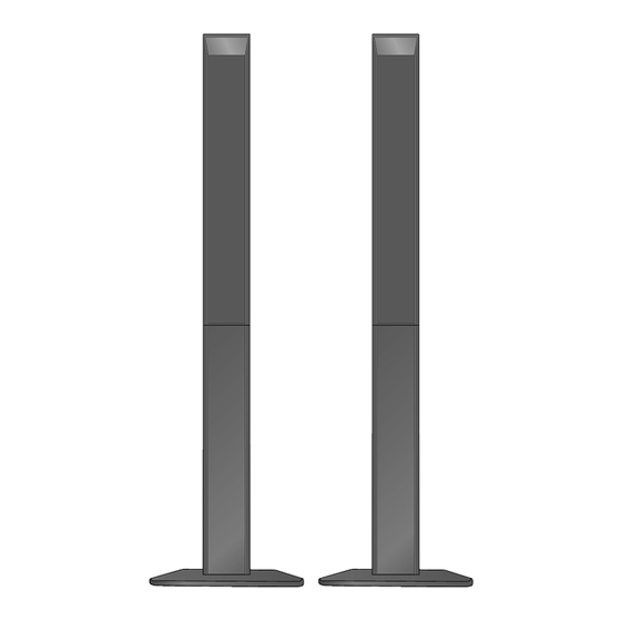
- Page 3 SB-HF950P 1 System Combination 1.1. System Breakdown Note : The diagrams below show the breakdown for speaker combinations used in main unit systems. SB-PT950P-K consists of SB-HF950P-K (x2), SB-HS950P-K (x2), SB-HC950P-K (x1)
- Page 4 SB-HF950P 2 Assembling and Disassembling “ATTENTION SERVICER” Some chassis components may have sharp edges. Be careful when disassembling and servicing. 1. This section describes procedures for checking the operation of the major printed circuit boards and replacing the main components.
- Page 5 SB-HF950P 2.2. Disassembly of Upper box 2.3. Disassembly of Upper rear assembly cabinet Follow (step 1) to (step 4) in item 2.2. Step 1: Remove the white (+) and blue (-) wires. Step 2: Pull out the speaker cable from the groove.
- Page 6 SB-HF950P 2.4. Disassembly of Woofer 1 2.5. Disassembly of Woofer 2 Follow (step 1) to (step 4) in item 2.2. Follow (step 1) to (step 4) in item 2.2. Follow (step 1) to (step 2) in item 2.3. Follow (step 1) to (step 2) in item 2.3.
- Page 7 SB-HF950P 2.6. Disassembly of Terminal jack Follow (step 1) to (step 4) in item 2.2. Follow (step 1) to (step 2) in item 2.3. Step 3: Remove terminal jack as arrow shown. Step 1: Detach the black (-) and red (+) wires.
- Page 8 SB-HF950P 2.7. Disassembly of Lower box assembly Follow (step 1) to (step 4) in item 2.2. Step 1: Pull out the speaker cable from the ridges. Step 2: Pull out the speaker cable from the groove inside by using hand.
- Page 9 SB-HF950P 2.8. Disassembly of Lower rear 2.9. Disassembly of Base stand cabinet assembly assembly Follow (step 1) to (step 4) in item 2.2. Follow (step 1) to (step 4) in item 2.2. Follow (step 1) to (step 7) in item 2.7.
- Page 10 SB-HF950P 2.10. Assembly of Front Speakers...
- Page 11 SB-HF950P 3 Connection of the Speaker Cables · Be sure to connect speaker cables before connecting the AC power supply cord. · The load impedance of any speaker used with this unit must be 6 Ω. · Be sure to connect the cable from the right speaker to the right terminal and the cable from the left speaker to the left terminal.
- Page 12 SB-HF950P Positioning the speakers...
- Page 13 SB-HF950P Note on speaker use · Use only supplied speakers. Using other speakers can damage the unit, and sound quality will be negatively affected. · You can damage your speakers and shorten their useful life if you play sound at high levels over extended periods.
- Page 14 SB-HF950P 4 Connection of the Wiring Diagram...
- Page 15 SB-HF950P 5 Exploded view 5.1. Cabinet Parts Location...
- Page 16 SB-HF950P 5.2. Packaging The diagram below shows the packaging for speakers in SB-PT950P-K.
- Page 17 SB-HF950P 6 Replacement Parts List Notes : · Important safety notice : When replacing any of these components, be sure to use only manufacturer’s specified parts shown in the parts list. · [M] markings in the Remarks columns indicates parts supplied by PAVCSG.
Need help?
Do you have a question about the SB-HF950P and is the answer not in the manual?
Questions and answers