Table of Contents
Advertisement
Thank you for purchasing a Hisaka Plate Heat Exchanger.
Manuals for the HISAKA Plate Heat Exchanger consist of the following seven related documents.
1. Installation Manual, 2. Operation and Maintenance Manual, 3. Gasketting Manual (Total 10 Models), 4. Plate
Cleaning Manual, 5. "Slit-In" Type Gasketting Manual, 6. Mixed Gasket Materials Manual, and 7. Strainer
Maintenance Manual.
These documents are available at our website (http://www.hisaka.co.jp/english).
Drawings (Plate Arrangement Drawing and Assembly Drawing) of supplied model are to be supplied with the
equipment.
Use as directed in these Manuals for safe and proper operation and maintenance.
Keep these Manuals in hand.
All description details, including appearance and specifications, presented in this manual are subject to change for
improvement without prior notice. For the latest information, please refer to our website, if necessary.
2 Operation and Maintenance Manual
Plate Heat Exchanger
Advertisement
Table of Contents

Related Manuals for HISAKA UX Series

Summary of Contents for HISAKA UX Series
- Page 1 Thank you for purchasing a Hisaka Plate Heat Exchanger. Manuals for the HISAKA Plate Heat Exchanger consist of the following seven related documents. 1. Installation Manual, 2. Operation and Maintenance Manual, 3. Gasketting Manual (Total 10 Models), 4. Plate Cleaning Manual, 5.
- Page 2 <Disclaimer> HISAKA accepts no liability for any failures in the function or performance of the equipment caused by use of any other than genuine parts. HISAKA accepts no liability for any injuries or damage borne by the user, caused by use of any other than genuine parts..
-
Page 3: Table Of Contents
HISAKA Plate Heat Exchanger Operation and Maintenance Manual Table of Contents Safety Precautions P1, 2 Names of Components Components Details Nameplate Accessories Consumables Model Description Tests Before Commissioning Operation Operation Shutdown Long-term Storage/Preservation Maintenance P8 to 15 Troubleshooting P15, 16... -
Page 4: Safety Precautions
When the tightening bolts breaks during operation or disassembly, it is The gasket should be adhered with Hisaka’s “S-1", "F-2" contains an dangerous not only broken pieces are scattered, but also fluid may organic solvent. Breathing the volatile ingredients for a long time may splash from PHE. - Page 5 CAUTION Do NOT touch the side of plate pack and heat transfer plate edge. Do NOT freeze. The edge of a heat transfer plate is very sharp and may cut you. If freezing occurs in PHE, the heat transfer plates may be damaged. Be sure to wear cut-resistant gloves whenever touching heat transfer Drain out completely to avoid freezing in case of preservation in cold plate.
-
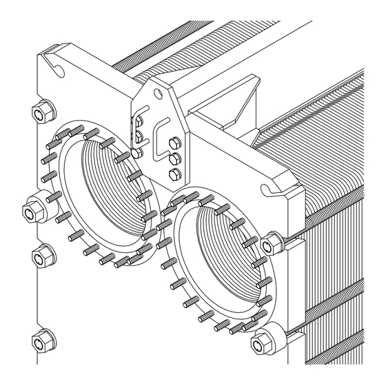
Page 6: Names Of Components
Names of Components PHE consists of the following parts. [NOTE] Plate Arrangement Drawing Refer to the " " for equipment specifications. Upper guide bar Tightening bolts and nuts E - Frame Upper guide bar E - Frame S-Frame S-Frame Stud bolt and nut Stud bolt and nut S-nozzle... -
Page 7: Components Details
Components Details B-Plate A-Plate Heat Transfer Plate The heat transfer plates comprise of the following three types. D-Plate (First heat transfer plate between the S, L, C, and E-Frames) E-Plate (Last heat transfer plate between the S, L, C, and E-Frames) ... -
Page 8: Nameplate
Fig. 4-1. Nameplate (sample) Accessories Any accessories, like a ratchet spanner, anchor bolt, thermometer, pressure gauge, etc., for HISAKA PHE are to be supplied as option upon request. 6 Consumables ... -
Page 9: Tests Before Commissioning Operation
Tests Before Commissioning Operation After installation, commissioning operation of the PHE is to follow the conditions below. System Test, Piping Test, Equipment Test Check the following nine items. If all of the items are not satisfied, do not operate the equipment and inform your supervisor or safety manager. ... -
Page 10: Operation
Operation The procedure for start-up depends on your use. Reconfirm your use and follow its procedure. General Starting Operation (No burnt or No frozen fluid) - Fullfill PHE chamber with media after all air is - Flow heating side - Flow heated side media. -
Page 11: Long-Term Storage/Preservation
Long-term Storage/Preservation If the unit has been used and long-term storage is required, PHE is to be placed in storage as below table. The storage conditions are depending on your application and the environment. Environment/Application Storage Procedure General use It must be completely drained and storage with empty condition to avoid failures such as alteration of any remaining liquid, corrosion in heat transfer plates, and damage to components from freezing. - Page 12 Apply lubricant the tightening bolts after cleaning all tightening bolt threads. Prepare the ratchet spanner or the automatic tightening device. Disassembly work Remove the tightening bolts and nuts as following steps by using a ratchet spanner or automatic tightening device. The following procedures shows an example of PHE with 14 tightening bolts and nuts.
- Page 13 12-2 Cleaning 12-2-1 Manual Cleaning Cleaning preparation Prepare a high-pressure washer or a soft brush, cleaning water, and dust cloths before cleaning the heat transfer plates. Prepare a work/step platform for large PHE because heat transfer plate can clean with suspending on the upper guide bar. ...
- Page 14 12-3 Maintenance 12-3-1 Heat Transfer Plate Replacement Removing heat transfer plates Replace any heat transfer plate with deformation, corrosion, or erosion to a brand-new one. Please refer to “Plate Arrangement Drawing” and “Gasketting Manual” for heat transfer plate arrangement. Rail type of upper guide bar (not round type) - Slightly bend the bottom of the heat transfer plate.
- Page 15 2) Prepare appropriate adhesive for the plate gasket material. There are the following four types of adhesive. Use the adhesive HISAKA specified. Types of adhesive...
- Page 16 Plate gasket has two sides. It is correct when stamp and color marking can be seen. (Some models are exception.) Before gasketting, fix any twisting of gasket and check the front and back surfaces. 12-4 Inspection Be sure to perform the following inspections before assembling a Hisaka PHE. Checking of heat transfer plate arrangement GOOD –...
- Page 17 [NOTE] Tightening for the HISAKA PHE shall be managed by tightening lengths but not by torque counting by millimeters. It is not a problem if there might be some different tightening torque between each tightening bolt position.
-
Page 18: Troubleshooting
12-6 Leakage Detection Leakage detection shall be performed once assembly of PHE has been completed. Check if any leakages appear at top, bottom and both sides of plate pack by carrying out hydrostatic test. Testing pressure shall not exceed the design pressure. Maintain pressure for 10 minutes or longer. - Page 19 Symptom Possible cause(s) Remedy/ Solution Metal covering nozzle has crack and/or Replace a set of the S-Frames with a pin-hole due to corrosion etc. (Continued from the previous page) brand-new one. Welding part of metal covering nozzle Fluid is leaking to the outside from Inquire with our company whether the has crack and/or pin-hole.
- Page 20 MEMO...
- Page 21 Plate Arrangement Drawing <Sample> - The equipment number, applicable code etc. are indicated. - Equipment specification is indicated. such as: - Plate arrangement of Operating conditions, design heat transfer plates is pressure, test pressure, design indicated. temperature etc. - Plate arrangement and nozzle connection size are - Material components and painting - Summary for plate...
- Page 22 Assembly Drawing This is one example of the Assembly Drawing of a Hisaka Plate Heat Exchanger. The following information is described in the Assembly Drawing. - Describes the position, standard, and diameter for piping to be mounted. - Tightening length for the - Describes this equipment's weight.
- Page 23 Exploded View [e.g.: J-Type Heat Exchanger] 2 3-3-1 3-2-2 3-2-1 3-2-2 3-2-1 3-2-2 3-2-1 Back 7 3-2-2 3-1-1 4 1 3-3-2 Nameplate S4-Nozzle 1-1 S2-Nozzle 8 S3-Nozzle S1-Nozzle 10 Tightening bolt and nut Frame support 12 Lower guide bar (Square pipe) 5...
- Page 24 Exploded View [e.g.: P-Type Heat Exchanger] 6 12 2 14 4 3-3-1 3-2-2 3-2-1 3-2-2 3-2-1 3-2-2 3-2-1 3-2-2 Nameplate 3-1-1 Back 7 E4-Nozzle 13 1 E2-Nozzle 15 E3-Nozzle E1-Nozzle 1-1 S4-Nozzle 8 S2-Nozzle 3-3-2 S3-Nozzle 10 S1-Nozzle Tightening bolt and nut Guide bar support 16...
- Page 25 Exploded View [e.g.: Welded P-Type Heat Exchanger] 6 12 2 14 4 3-3-1 3-2-2 3-2-1 3-2-2 3-2-1 3-2-2 3-2-1 7 3-2-2 Nameplate 3-1-1 Back 13 E4-Nozzle E2-Nozzle 1 15 E3-Nozzle E1-Nozzle S4-Nozzle 3-3-2 1-1 S2-Nozzle S3-Nozzle 8 S1-Nozzle Tightening bolt and nut 10...
- Page 26 Exploded View [e.g.: BP2CL Type Heat Exchanger] 7 6 12 2 14 Nameplate C24-Nozzle 25 C22-Nozzle 4 23 C23-Nozzle 22 C21-Nozzle C2-Frame C14-Nozzle 20 C12-Nozzle 13 18 C13-Nozzle 17 15 C11-Nozzle C1-Frame L-Frame E4-Nozzle 16 E2-Nozzle 26 24 E3-Nozzle E1-Nozzle S4-Nozzle S2-Nozzle S3-Nozzle...
- Page 27 Inquiries Contact info for inquiries HISAKA WORKS, LTD., Heat Exchanger Div., Sales Department Osaka: 2-1-48, Higashi-Konoike-cho, Higashi-Osaka, Osaka, 578-0973, Japan Tel : +81-(0)72-966-9601 Fax : +81-(0)72-966-8923 Tokyo: KYOBASHI OM BLDG. 1-19-8, Kyobashi, Chuo-Ku, Tokyo, 104-0031, Japan Tel : +81-(0)3-5250-0760 Fax : +81-(0)3-3562-2759 Nagoya: Fujifilm Nagoya Bldg.
- Page 28 No.117 Xiangyuan Road, Changshu National New & Hi-tech Industrial Development Zone, Changshu City, Jiangsu Province 215542, P.R. China Fax : +86-512-5213-3008 HISAKA WORKS(CHINA)CO., LTD. SHANGHAI BRANCH (CHINA) Tel : +86-21-5211-0701 Room 1603, Shanghai Oriental Center, 699 West Nanjing Road, Shanghai 200041, P.R. China...
- Page 29 Please inform us the "MFG. Number" and "Model" described on the nameplate or Plate Arrangement Drawing and Assembly Drawing. For more information Hisaka Works, Ltd. official homepage (http://www.hisaka.co.jp/english/). Customer's memo Please fill in the table below with PHE information.
- Page 30 Location(s) of failure Symptom(s)
- Page 31 Hisaka Works, Ltd., Heat Exchanger Division acquires both ISO9001 and ISO14001 certification. HE-ME0013R23...
Need help?
Do you have a question about the UX Series and is the answer not in the manual?
Questions and answers