
Related Manuals for Robokits Robotic Arm 6 DOF

Summary of Contents for Robokits Robotic Arm 6 DOF
- Page 1 Robotic Arm 6 DOF Assembly Guide Robokits India http://www.robokits.co.in info@robokits.co.in Robokits World http://www.robokitsworld.com http://www.robokits.co.in http://www.robokitsworld.com Page 1 Robotic Arm 6 DOF Assembly Guide...
- Page 2 Overview 6 DOF Robotic Arm from Robokits is a robotic arm with 4 degrees of freedom joints and a Gripper. Its actuated using 6 Standard size servos out of which 4 are normal Nylon gears standard and 2 are Metal Gear High Torque servo motors.
- Page 3 Fix four 10 mm studs to base with four csk screws. You may have to push hard the screw from bottom. http://www.robokits.co.in http://www.robokitsworld.com Page 3 Robotic Arm 6 DOF Assembly Guide...
- Page 4 Fix six 50 mm spacers to the base with csk screws just as before. http://www.robokits.co.in http://www.robokitsworld.com Page 4 Robotic Arm 6 DOF Assembly Guide...
- Page 5 This is how the base will look after fixing all the studs. http://www.robokits.co.in http://www.robokitsworld.com Page 5 Robotic Arm 6 DOF Assembly Guide...
- Page 6 Now take a circle plate with holes for servo and castor wheels, 9 locknuts and 9 M3 long screws. http://www.robokits.co.in http://www.robokitsworld.com Page 6 Robotic Arm 6 DOF Assembly Guide...
- Page 7 Fix three castors on the base as shown in above picture. Now take a servo, 4 M3 Long screws, and 4 lock nuts. http://www.robokits.co.in http://www.robokitsworld.com Page 7 Robotic Arm 6 DOF Assembly Guide...
- Page 8 Fix the servo motor to the base as shown. The final assembly will look like the picture above. http://www.robokits.co.in http://www.robokitsworld.com Page 8 Robotic Arm 6 DOF Assembly Guide...
- Page 9 Take assembled plate with servo and castors and six M3 small screws. http://www.robokits.co.in http://www.robokitsworld.com Page 9 Robotic Arm 6 DOF Assembly Guide...
- Page 10 Fix the plate and servo controller pcb to the base as shown. The base assembly is now complete. http://www.robokits.co.in http://www.robokitsworld.com Page 10 Robotic Arm 6 DOF Assembly Guide...
- Page 11 Optionally you can also mount castor plate inverted. http://www.robokits.co.in http://www.robokitsworld.com Page 11 Robotic Arm 6 DOF Assembly Guide...
- Page 12 The round plate has 2 countersunk holes towards the edge. The horn should be fixed to the countersunk holes side only. You may receive servo horn screw in silver or black color. http://www.robokits.co.in http://www.robokitsworld.com Page 12 Robotic Arm 6 DOF Assembly Guide...
- Page 13 When these parts are seen from top , they will look like the picture above. http://www.robokits.co.in http://www.robokitsworld.com Page 13 Robotic Arm 6 DOF Assembly Guide...
- Page 14 2 csk screws are inserted from bottom and locknut is on top side. See next picture for bottom view. http://www.robokits.co.in http://www.robokitsworld.com Page 14 Robotic Arm 6 DOF Assembly Guide...
- Page 15 Note that 2 CSK screws are inserted from bottom and nut is on top side. This is important otherwise the castor will touch the screw and restrict the movement of base rotation. http://www.robokits.co.in http://www.robokitsworld.com Page 15 Robotic Arm 6 DOF Assembly Guide...
- Page 16 Make sure that plate is not too loose or tight. Test with moving slider in software. *Note : Please read manual of servo controller first before performing this step. http://www.robokits.co.in http://www.robokitsworld.com Page 16 Robotic Arm 6 DOF Assembly Guide...
- Page 17 Mount a metal gear servo with back attached to the clamp with M3 Long screws and locknuts as shown in picture. http://www.robokits.co.in http://www.robokitsworld.com Page 17 Robotic Arm 6 DOF Assembly Guide...
- Page 18 Take out part with 2 servos and top mount for it. Also take 2 20mm studs and 4 M3 Small screws. http://www.robokits.co.in http://www.robokitsworld.com Page 18 Robotic Arm 6 DOF Assembly Guide...
- Page 19 Fix two 20 mm studs in holes with 2 M3 small screws as shown. Also fix 4 rubber mounts available in metal gear servo accessory pack to metal gear servo as shown above. Take out eight M3 Long screws and locknuts for next assembly step. http://www.robokits.co.in http://www.robokitsworld.com Page 19 Robotic Arm 6 DOF Assembly Guide...
- Page 20 Mount servos to the plate with 4 M3 Long screws and locknuts. Fix the top plate with bottom through 20 mm studs with 2 M3 Small screws. http://www.robokits.co.in http://www.robokitsworld.com Page 20 Robotic Arm 6 DOF Assembly Guide...
- Page 21 Now connect all the motors to servo controller and neutralize them. Keep the servo controller powered on while assembly so all servos will be locked to centre position. http://www.robokits.co.in http://www.robokitsworld.com Page 21 Robotic Arm 6 DOF Assembly Guide...
- Page 22 Fix plate with 2 servo horns to the 2 ready assemblies. Keep it perpendicular to each other. http://www.robokits.co.in http://www.robokitsworld.com Page 22 Robotic Arm 6 DOF Assembly Guide...
- Page 23 Keeping the servos powered lock both servos with screws provided in servo accessory pack. Now you can power off the servo controller for next few steps. http://www.robokits.co.in http://www.robokitsworld.com Page 23 Robotic Arm 6 DOF Assembly Guide...
- Page 24 Mount 2 50 mm studs with M3 small screws as shown in picture above. http://www.robokits.co.in http://www.robokitsworld.com Page 24 Robotic Arm 6 DOF Assembly Guide...
- Page 25 On the back side, put the part with 4 holes and lock it with 2 M3 small screws and 2 Locknuts as shown in picture. http://www.robokits.co.in http://www.robokitsworld.com Page 25 Robotic Arm 6 DOF Assembly Guide...
- Page 26 Take wrist rotate servo. Put 2 rubber mounts on mounting holes from servo accessory pack. http://www.robokits.co.in http://www.robokitsworld.com Page 26 Robotic Arm 6 DOF Assembly Guide...
- Page 27 Fix the servo to mini servo mounting plate with 2 M3X10 CSK screws and M3 Nuts. http://www.robokits.co.in http://www.robokitsworld.com Page 27 Robotic Arm 6 DOF Assembly Guide...
- Page 28 If not already prepared, prepare wrist mount part with a servo horn as shown in top inset images. Neutralize the wrist servo and mount it on servo shaft parallel to body. http://www.robokits.co.in http://www.robokitsworld.com Page 28 Robotic Arm 6 DOF Assembly Guide...
- Page 29 Fix the wrist joint servo horn to servo with screw. Mount a 50 mm stud in centre hole with M3 small screw. http://www.robokits.co.in http://www.robokitsworld.com Page 29 Robotic Arm 6 DOF Assembly Guide...
- Page 30 Take the back part of wrist joint, put wrist rotate servo mount between front and back part and fix the back part with a M3 small screw and a locknut as shown above. http://www.robokits.co.in http://www.robokitsworld.com Page 30 Robotic Arm 6 DOF Assembly Guide...
- Page 31 Neutralize the wrist rotate servo and fix the gripper on it such that its almost parallel to the wrist rotate servo plate. http://www.robokits.co.in http://www.robokitsworld.com Page 31 Robotic Arm 6 DOF Assembly Guide...
- Page 32 Lock the gripper to wrist rotate servo with a lock screw provided in accessory pack of mini servo. You will have to put screwdriver through gripper’s hole in centre between tow jaws. http://www.robokits.co.in http://www.robokitsworld.com Page 32 Robotic Arm 6 DOF Assembly Guide...
- Page 33 Neutralize a standard servo, put the gripper jaws to approximate mid position and fix servo to gripper horn and secure it with a locking screw available in accessory pack from top. Mechanical assembly is now complete. Next step is connection and cabling. http://www.robokits.co.in http://www.robokitsworld.com Page 33 Robotic Arm 6 DOF Assembly Guide...
- Page 34 Connect 3 servo extension cables to gripper jaw, gripper rotate and wrist servos as the cables will not be enough to reach servo controller. http://www.robokits.co.in http://www.robokitsworld.com Page 34 Robotic Arm 6 DOF Assembly Guide...
- Page 35 You can mark the end connectors with servo name or number so that connection will be easy at the end. Follow the pictures to see steps in cabling. http://www.robokits.co.in http://www.robokitsworld.com Page 35 Robotic Arm 6 DOF Assembly Guide...
- Page 36 Page 36 Robotic Arm 6 DOF Assembly Guide...
- Page 37 Page 37 Robotic Arm 6 DOF Assembly Guide...
- Page 38 Page 38 Robotic Arm 6 DOF Assembly Guide...
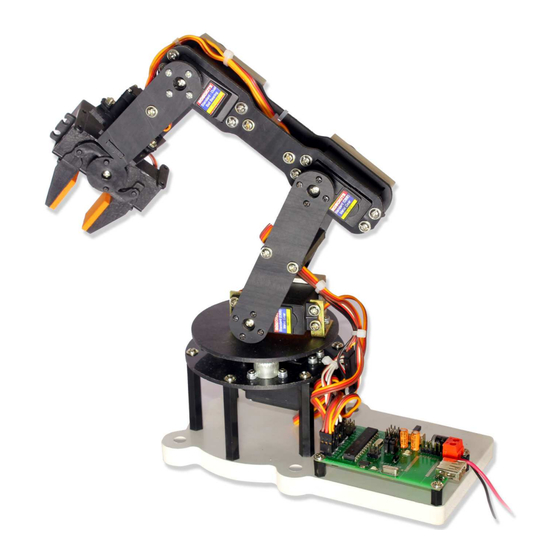
- Page 39 Assembly is now complete. http://www.robokits.co.in http://www.robokitsworld.com Page 39 Robotic Arm 6 DOF Assembly Guide...
- Page 40 The final robot should look like shown above. Go through the servo controller document for programming and using the robotic arm. http://www.robokits.co.in http://www.robokitsworld.com Page 40 Robotic Arm 6 DOF Assembly Guide...
-
Page 41: Service And Support
Robokits site http://www.robokits.co.in ) maintains current contact information for all Robokits products. Disclaimer Copyright © Robokits India, 2013 Neither the whole nor any part of the information contained in, or the product described in this manual, may be adapted or reproduced in any material or electronic form without the prior written consent of the copyright holder.
Need help?
Do you have a question about the Robotic Arm 6 DOF and is the answer not in the manual?
Questions and answers