Table of Contents
Advertisement
Quick Links
799000347 / Rev. 10 / 2018-07-23
Translation of the original operating manual
Operating Manual
SERIES P40-000
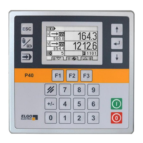
Programmable 1 or 2 Axes Position Controller
Position Controller for 1 or 2 Axes
Manual, Single or Program operation
LCD display with 7 menu languages
16 freely configurable inputs & outputs
Optionally with 12 bit analog output
Useful functions like referencing,
tool offset and batch counter
Simple and intuitive handling
Integrated diagnosis mode
Optional RS232 interface
Quick panel mounting
Advertisement
Table of Contents

Related Manuals for ELGO Electronic P40-000 Series


Summary of Contents for ELGO Electronic P40-000 Series
- Page 1 799000347 / Rev. 10 / 2018-07-23 Translation of the original operating manual Operating Manual SERIES P40-000 Programmable 1 or 2 Axes Position Controller Position Controller for 1 or 2 Axes Manual, Single or Program operation LCD display with 7 menu languages ...
- Page 2 +49 (0) 7731 9339 – 0 +49 (0) 7731 2 13 11 info@elgo.de Document- No. 799000347 Document- Name P40-000-MA-E_30-18 Document- Revision Rev. 10 Issue Date 2018-07-23 Copyright © 2018, ELGO Electronic GmbH & Co. KG - 2 -...
-
Page 3: Table Of Contents
Contents 1 Contents Contents ..................... 3 General, Safety, Transport and Storage ........... 6 Information Operating Manual ................6 Explanation of Symbols ..................6 Statement of Warranties ..................7 Demounting and Disposal ..................7 General Causes of Risk ..................7 Personal Protective Equipment ................7 Conventional Use .................... - Page 4 Contents System Menu ..................36 10.1 System: Setup ....................36 10.2 System: System-Times ..................39 10.3 System: I/O Configuration .................. 40 10.4 System: Default Parameters ................44 Password Menu ................45 Contrast Menu .................. 45 Diagnosis / Error Messages Menu ........... 46 13.1 Diagnosis ......................
- Page 5 Contents Image Directory Figure 1: P40-000 controller with panel housing ..................9 Figure 2: Dimensions of the P40 controller ....................10 Figure 3: Key Functions ........................... 13 Figure 4: Display Functions ........................14 Figure 5: Manual Operation ........................15 Figure 6: Single Operation ........................16 Figure 7: Program Operation ........................
-
Page 6: General, Safety, Transport And Storage
General, Safety, Transport and Storage 2 General, Safety, Transport and Storage Information Operating Manual This manual contains important information regarding the handling of the device. For your own safety and operational safety, please ob- serve all safety warnings and instructions. Precondition for safe operation is the compliance with the specified safety and handling instruc- tions. -
Page 7: Statement Of Warranties
General, Safety, Transport and Storage Statement of Warranties The producer guarantees the functional capability of the process engineering and the selected parameters. Demounting and Disposal Unless acceptance and disposal of returned goods are agreed upon, demount the device considering the safety instructions of this manual and dispose it with respect to the environment. -
Page 8: Conventional Use
General, Safety, Transport and Storage Conventional Use The product described in this manual was developed to execute safety-related functions as a part of an entire assembly or machine. The ELGO position controller P40-000 only serves for positioning applications. CAUTION! Danger through non-conventional use! Non-intended use and non-observance of this operating manual can lead to dangerous situations. -
Page 9: Product Features
Product Features 3 Product Features The position controller of the P40 series is used for simple positioning applications, e. g. with wood or sheet metal processing machines. The main advantage of this controller is the simple, easy and fast entry of required positions and quantities. -
Page 10: Technical Data
Technical Data 4 Technical Data Identification The type label serves for the identification of the unit. It is located on the housing of the sensor and gives the exact type designation ( 18) with the corresponding part number. Furthermore, the type label contains a unique, traceable device number. -
Page 11: Technical Data Controller
Technical Data Technical Data Controller Technical Data P40-000 (standard version) Mechanical Data Housing panel housing Housing material front plate: aluminium housing: galvanized steel sheet Front plate dimensions W x H = 144 x 144 mm Panel cutout W x H = 138 x 138 mm Keyboard membrane keyboard Installation depth... -
Page 12: Installation And First Start-Up
Installation and First Start-Up 5 Installation and First Start-Up CAUTION Please read the operating manual carefully before using the device! Strictly observe the Installation instructions! In case of damage caused by failure to observe this operating manual, the warranty expires. ELGO is not liable for any secondary damage and for damage to persons, property or assets. -
Page 13: Design Und Function
Design und Function 6 Design und Function Key Functions Escape Menu navigation Operating mode Functional keys START Input field STOP Figure 3: Key Functions Switchover between “Manual” and “Single” mode Operation mode “Program” (only if program mode is activated) To enter the parameter level (press for 3 seconds) and to exit the parameter level or a submenu (press shortly) Select or confirm (ENTER button) Cursor navigation „down“... -
Page 14: Display Functions
Design und Function Display Functions Program number Program block number Symbol operating mode Absolute- / incremental Actual position position Target position Options Piece counter Program counter Browse through data blocks Figure 4: Display Functions NOTE! The display elements can vary depending on operating mode and configuration. - 14 -... -
Page 15: Handling & Operating Modes
Handling & Operating Modes 7 Handling & Operating Modes Operating Modes Depending on the parameter setting, the screen display and assignment of the function keys can vary. 7.1.1 Manual Operation In this mode the axes can be moved manually (manual inching). To do this, select the corresponding axis with the cursor and change the position by using the functional keys F1 / F3. - Page 16 Handling & Operating Modes 7.1.2 Single Operation This mode allows moving all active axes simultaneously after entering the desired target values and confirmation by the START key. Figure 6: Single Operation Displays the actual position of the respective axis Incremental positioning: target value is an absolute position ...
- Page 17 Handling & Operating Modes 7.1.3 Program Operation When using the program mode, the user has the possibility to summarize several program blocks into one pro- gram. Depending on the configuration, different program sequences are possible. Figure 7: Program Operation Enter and confirm a program number Incremental positioning: target value is an absolute position ...
-
Page 18: Referencing An Axis
Handling & Operating Modes After entering the required data sets, the program end has to be marked. For this, the F2 key must be pressed during the cursor is in the input field for the block number. The defined program end will then be marked with the letter “E”... -
Page 19: Menu Structure And Parameter Levels
Menu Structure and Parameter Levels 8 Menu Structure and Parameter Levels Operating modes Service (press ESC for 3 seconds) parameter axis manual mode X-axis single mode distances program mode times analog (optionally) measuring system (optionally) settings Y-axis distances times analog (optionally) measuring system (optionally) settings system... -
Page 20: Axis Menu
Axis Menu 9 Axis Menu Parameter Axis: Distances This menu is used to set relevant distances for the X- and Y-axis separately. Distances. Access to parameters concerning distances e.g. speeds etc. Times Access to parameters concerning times e.g. position reached, zero speed monitoring, rotary encoder etc. Settings Access to the general axis parameters Slow forward... - Page 21 Axis Menu Slow forward / slow backward = middle speed This parameter defines the distance at which the controller switches from high speed to slow speed before reaching the target position. Creep forward / creep backward = slow speed This parameter defines the distance at which the controller switches from slow speed to creep speed before reaching the target position.
- Page 22 Axis Menu Example: Positioning with 3 speeds For the parameter setting generally applies: Slow speed Creep speed > Correction stop Slow speed: 20.0 mm Creep speed: 10.0 mm Correction stop: 1.0 mm Fast Slow speed Creep speed Position reached: 100.0 mm Correction Stop Slow Middle...
- Page 23 Axis Menu Forced loop If the actual value is during an absolute positioning within the range target value +/− value of forced loop window, a forced loop is moved. Reference value This parameter is used to define reference value resp. reference position. Retract length When activating the external retract input, the axis moves depending on the retract mode setting (see ...
-
Page 24: Parameter Axis: Times
Axis Menu Parameter Axis: Times This menu is used to set relevant time parameters for the X- and Y-axis separately. Distances Access to parameters concerning distances e.g. speeds etc. Times. Access to parameters concerning times e.g. position reached, zero speed monitoring, rotary encoder etc. Settings Access to the general axis parameters Position reached... - Page 25 Axis Menu Position reached The output signal is statically if this time parameter is set to 0 or wiping if a time is defined here. The output will be active as soon the according axis has reached the target position. Spindle compensation In the peak of the loop drive the drive signals switch off.
-
Page 26: Parameter Axis: Settings
Axis Menu Parameter Axis: Settings This menu is used to set general parameters for the X- and Y-axis separately. Distances Access to parameters concerning distances e.g. speeds etc. Times Access to parameters concerning times e.g. position reached, zero speed monitoring, rotary encoder etc. Settings. - Page 27 Axis Menu Axis type This parameter is used to define the type of axis (for each axis separately). IN: „Encoder“ for usage with incremental encoder resp. measuring systems IN: „Analog“ for usage with analog measuring systems resp. sensors ...
- Page 28 Axis Menu Drive signals Mode 3 2 speeds Speed = output signals 2 + 3 Output 4 set direction backward Output signals Creep forward Slow forward Fast forward Creep backward Slow backward Fast backward Drive signals = Mode 4 ...
- Page 29 Axis Menu Drive signals = Mode 6 3 speeds Binary coded Output 1 = forward Output 4 = backward Outputs 2+3 = speed Output signals Creep forward Slow forward Fast forward Creep backward Slow backward Fast backward Drive signals = Mode 7 ...
- Page 30 Axis Menu Spindle compensation mode without (no spindle compensation) negative spindle compensation − positive spindle compensation + with forced loop – with forced loop + Software end-position both enabled negative disabled positive disabled ...
- Page 31 Axis Menu Piece counter This parameter is used to define the piece counter function for the Single Mode: without piece counter auto decrement * auto decrement + Stop * auto increment * auto decrement/ increment * ...
-
Page 32: Parameter Axis: Analog - Optional
Axis Menu Parameter Axis: Analog - optional This menu is used to set the optional analog parameters for the X- and Y-axis separately. Distances Access to parameters concerning distances e.g. speeds etc. Times Access to parameters concerning times e.g. position reached, zero speed monitoring, rotary encoder etc. Analog. - Page 33 Axis Menu Please note: The optional analog parameters are only displayed in the menu “axis parameter” if an analog output has been previously assigned in the menu parameter axis X-/Y-axis settings axis type to the cor- responding axis. See figure 11 and section 14.2. Setting for a regulated PID analog output: Setting for an unregulated analog output: Y-axis system...
- Page 34 Axis Menu D-portion Differential voltage: setting 1 ... 1000 General: The D-controller (differential controller) determines the control value from the derivative with respect to time of the offset. P40: At offset a short voltage pulse proportional to the rate of change will be put out to compensate quickly without sacrificing the stability of the control loop permanently.
-
Page 35: Parameter Axis: Measuring System - Optional
Axis Menu Parameter Axis: Measuring System - optional This menu is used to calibrate analog inputs. The submenu "measuring system" is only relevant for devices which are optionally equipped with an analog input ( 18 Type Designation). Please note: The submenu "Measuring system" appears only under "Axis parameters", if an analog measuring system has been assigned to the corresponding axis (parameter axis ... -
Page 36: System Menu
System Menu 10 System Menu 10.1 System: Setup Setup. Access to the system parameters System-Times Access to system parameters concerning times I/O-configuration Here the inputs and outputs can be assigned Default parameter Reset the parameters to factory settings Language Axes active (only with two-axes-version) Piece Counter program Auxiliary Counter Number of programs... - Page 37 System Menu Language German English French Spanish Italian Polish Chinese Axes active (only with two-axes-version) X-axis X-axis and Y-axis Piece counter program This parameter is used to set the mode of the piece counter during “program” operation. without no piece counter activated ...
- Page 38 System Menu Next set stepping The following options can be selected for “next set stepping”: without no next step setting activated quantity reached after expiration of the piece counter of the current set, the next set will be loaded ...
-
Page 39: System: System-Times
System Menu 10.2 System: System-Times Setup Access to the system parameters System-Times Access to system parameters concerning times I/O-configuration Here the inputs and outputs can be assigned Default parameter Reset the parameters to factory settings Next set stepping Clamping off Editmode timeout Piece counter prog Clamp aux function... -
Page 40: System: I/O Configuration
System Menu 10.3 System: I/O Configuration Setup Access to the system parameters System-Times Access to system parameters concerning times I/O-configuration Here the inputs and outputs can be assigned Default parameter Reset the parameters to factory settings Input function Input logic Output function Output logic 10.3.1 Input Functions... - Page 41 System Menu Incremental positioning negative If this input is active, the incremental positioning is in negative direction, if incremental positioning is externally configured (parameter axis X-/Y-axis settings incremental positioning external). Incremental positioning positive If this input is active, the incremental positioning is in negative direction, if incremental positioning is externally configured (parameter axis ...
- Page 42 System Menu 10.3.2 Output Functions Position reached (wiping / statically) If 0.0 s is entered in parameter axis X-/Y-axis times pos. reached, the output switches statically i.e. the output is active, after the target value has been reached. If a wiping time between 0.1 …...
- Page 43 System Menu Auxiliary function In the single and program mode these outputs are set according to the defined time in parameter system system-times clamp aux function Clamping This output is set before a positioning and is reset after a positioning (e. g. for a clamping system or in order to activate resp.
-
Page 44: System: Default Parameters
System Menu 10.3.3.3 Linking of Outputs with Functions Chapter 15 I/O Configuration Notation Table contains an overview of all functions which can be assigned to the inputs. After selecting a function via parameter system I/O-configuration output function by using the navigation buttons. -
Page 45: Password Menu
Password Menu 11 Password Menu The password for the PIN query is entered in the Password menu. The entered password must be confirmed by pressing button NOTE! The parameter level is saved by a password. 250565 Required PIN CODE: After entering the password / PIN code, all parameters can be edited. 12 Contrast Menu This menu is used to adjust the contrast of the display. -
Page 46: Diagnosis / Error Messages Menu
Diagnosis / Error Messages Menu 13 Diagnosis / Error Messages Menu 13.1 Diagnosis This menu contains a function to test the hardware and to display the current installed hard- and software ver- sion. Inputs Outputs Keypad Version/Info ... -
Page 47: Parameter Lists
Parameter Lists 14 Parameter Lists 14.1 Parameter Axis: Distances Table 2: Axis parameter list: Distances Function Range Default Setting Slow forward 0.0 ... 9999.9 * 15.0 15.0 Creep forward 0.0 ... 9999.9 * Correction stop forward 0.0 ... 9999.9 * 15.0 Slow backward 0.0 ... -
Page 48: Parameter Axis: Analog - Optional
Parameter Lists 14.3 Parameter Axis: Analog - optional Please note: The optional analog parameters are only displayed in the menu “axis parameter” if an analog or PID output has been previously assigned in the menu parameter axis X-/Y-axis settings axis type to the corresponding axis (... -
Page 49: Parameter Axis: Settings
Parameter Lists 14.2 Parameter Axis: Settings Table 6: List of general axis parameters Function Range Default Setting Axis type Measuring system - - - drive outputs Encoder - - - Digital Encoder - - - PID + Digital Analog - - - Digital Encoder - - -... -
Page 50: System: Setup
Parameter Lists 14.3 System: Setup Table 7: List of system parameters: setup Function Range Default Setting Language English / Francais / Castellano / English Italiano / Polski / Chinese / Deutsch Axes active (only with two-axes-version) X-axis X-axis + Y-axis X-axis + Y-axis Piece Counter program decrement... -
Page 51: O Configuration Notation Tables
I/O Configuration Notation Tables 15 I/O Configuration Notation Tables The following tables are used to note an individual input and output configuration: Table 9: Notation table for input configurations Input Logik ST4 (with option 16 I/O configurable) Function default customer Switch endpos X-min Switch endpos X-max Switch endpos Y-min... - Page 52 I/O Configuration Notation Tables Table 10: Notation table for output configurations Logic Output ST6 (with option 16 I/O configurable ) default customer Function Drive signal 1 X-axis Drive signal 2 X-axis Drive signal 3 X-axis Drive signal 4 X-axis Drive signal 1 Y-axis Drive signal 2 Y-axis Drive signal 3 Y-axis Drive signal 4 Y-axis...
-
Page 53: Connections
Connections 16 Connections 16.1 Plug Arrangement MCC1 MCC2 Figure 15: Plug arrangement Plug No. Purpose ST1 Measuring system connection ST2 Measuring system connection (only at 2-axes-version) ST3/ST4 Digital inputs ST5/ST6 Digital outputs ST7 Analog output (PID) ST8 Analog output 2 (PID) (only at 2-axes-version) ST9 Voltage supply MCC1 Control signal 1 (PID)* MCC2 Control signal 2 (PID)* (only 2-axis version) -
Page 54: Pin Assignment
Connections 16.2 Pin Assignment (default assignment – factory settings) Table 11: Measuring system connections Incremental Measuring System Incremental Measuring System 0 V / GND 0 V / GND + 24 VDC out (optionally 5 VDC) + 24 VDC out (optionally 5 VDC) Channel A Channel A Channel B... - Page 55 Connections Table 14: Analog / PID output connections Table 15: Power supply connections Analog output / PID output Power Supply input ST7/8 0 V / GND 0 V / GND + 24 VDC Analog out Table 16: Analog output / motor drive controller MCC MCC1 Analog out / Motor Drive Controller MCC MCC2 Analog out / Motor Drive Controller MCC...
-
Page 56: Connection Example Diagram
Connections 16.3 Connection Example Diagram 0 V (GND) + 24 VDC (output) 0 V (GND) Drive signal 1 Axis X + 24 VDC (output) Drive signal2 Axis X Protection earth Drive signal3 Axis X Drive signal4 Axis X Position reached X Quantity reached X 0 V (GND) Controller enable X... -
Page 57: Disturbances, Maintenance, Cleaning
Disturbances, Maintenance, Cleaning 17 Disturbances, Maintenance, Cleaning This chapter describes possible causes for disturbances and measures for their removal. In case of increased disturbances, please follow the measures for fault clearance in chapter 17.1. In case of disturbances that cannot be eliminated by following the advice and the fault clear- ance measures given here, please contact the manufacturer (see second page). -
Page 58: Maintenance
Disturbances, Maintenance, Cleaning 17.3 Maintenance The device is maintenance-free. WARNING! Danger through non-conventional maintenance! Non-conventional maintenance can lead to severe injuries and damage of property. Therefore: Maintenance works may only be completed by staff that has been authorized and trained by the operator. 17.4 Cleaning WARNING! The device can only be cleaned with a damp cloth, do not use aggressive cleanser! -
Page 59: Type Designation
Type Designation 18 Type Designation - 000 XXXX Device Designation: P40 = Position Controller for 1 or 2 axes Version: 000 = standard version 001 = first special version 002 = second special version (etc.) Power Supply Voltage: 024 = 24 VDC (+10 / -20 %) Encoder Inputs (per Axis): = input is not available = A, B, Z (PNP) -
Page 60: Accessories
Accessories 19 Accessories The following table shows the available accessories as well as the respective order designation: Table 17: Accessories Order designation Description NG 13.0 Power pack for AC-supply (primary: 115/230 VAC, secondary: 24 VDC/600 mA) Relay card with 8 changeover relays (28 VDC/250 VAC / 12 A) P40 Interface Cable Interface cable for PC connection (with RJ45 connector and female 9-pin SUB-D) - 60 -... - Page 61 Accessories Notes: - 61 -...
- Page 62 Accessories Notes: - 62 -...
-
Page 63: Index
Index 20 Index Accessories ............. 60 Operating area ..........12 Accident prevention regulations......6 Operating Modes ..........9 Activation of the device ........12 Operational safety ..........6 Analog Input Calibration ........35 Output Functions ..........42 Axis Menu ............20 Output-Logic Assignment ......... - Page 64 Document- No.: 799000347 / Rev. 10 ELGO Electronic GmbH & Co. KG Measuring | Positioning | Control Document- Name: P40-000-MA-E_30-18 Carl - Benz - Str. 1, D-78239 Rielasingen Subject to change - © 2018 Fon:+49 (0) 7731 9339-0, Fax:+49 (0) 7731 28803 Internet: www.elgo.de, Mail: info@elgo.de...
Need help?
Do you have a question about the P40-000 Series and is the answer not in the manual?
Questions and answers