Table of Contents
Advertisement
Advertisement
Table of Contents

Related Manuals for Laser Technology UltraLyte


Summary of Contents for Laser Technology UltraLyte
- Page 1 For Internal Use Only. Not for Distribution.
-
Page 2: Limited Warranty
For Internal Use Only. Not for Distribution. Laser Technology, Inc. (LTI) warrants the UltraLyte to be in good working order for a period of one year from the date of purchase from LTI or an authorized LTI product dealer. Should the product fail to be in good working order at any time during the warranty period, LTI will, at its option, repair or replace the product at no additional charge, except as set forth below. - Page 3 Return Merchandise Authorization (RMA) number before returning your product. Contact us at: Laser Technology 7070 South Tucson Way Englewood, CO 80112 USA Phone: 303-649-1000 Web Site: www.lasertech.com Electronic Copy of LTI’s UltraLyte User’s Manual – 7 Edition June 1998...
- Page 4 Laser Technology, Inc. UltraLyte and UltraLyte LR laser speed and ranging instruments. The UltraLyte has a large number of options and is highly configurable. This manual describes all the possible options. Your particular UltraLyte instrument may not have all the options described.
-
Page 5: Precautions
Avoid staring directly at the laser beam for prolonged periods. The UltraLyte is designed to meet FDA eye safety requirements and is classified as eye- safe to Class 1 limits, which means that virtually no hazard is associated with directly viewing the laser output under normal conditions. - Page 6 For Internal Use Only. Not for Distribution. Laser Technology UltraLyte Quick Reference Legend: Power On/Off UL200 Distance Measurement SURVEY Power On Horizontal distance SURVEY OPTIONS SURVEY Slope distance BACKLIGHT Power Off Press and release SURVEY OPTIONS EDIT DN Vertical distance...
- Page 7 Mute EDIT DN MENU MUTE TEST Auto repeat Power conservation MENU ALL On EDIT UP BACKLIGHT EDIT DN Electronic Copy of LTI’s UltraLyte User’s Manual – 7 Edition June 1998...
-
Page 8: Table Of Contents
Unfolding the Stock for Right-handed Operation Measuring the Distance .....................9 Taking the Measurements......Adjusting the Length and Angle ....10 Notes on Using TOD ........Refolding the Stock ........10 Electronic Copy of LTI’s UltraLyte User’s Manual – 7 Edition June 1998... - Page 9 NITS Caring for the Scope ........Notes ............40 Checking the Display Screen ............ ONTINUOUS Resetting Factory Option Defaults ........UTING THE NSTRUMENT ..OWER ONSERVATION NTERVALS Electronic Copy of LTI’s UltraLyte User’s Manual – 7 Edition June 1998...
- Page 10 Survey Data Message Format ....64 Criterion Download Format ......65 Version ID Requests ........65 Survey Data Message Format ....66 20-20 Download Format ......68 Version ID Requests ........68 Speed/Range Data Message Format ..70 Electronic Copy of LTI’s UltraLyte User’s Manual – 7 Edition June 1998...
-
Page 11: Checking The Instrument
Basic UltraLyte Package - Turck 4-pin to HP 200/48 10-pin cable • UltraLyte instrument • Data collector and software • Two C batteries • User’s manual • Padded carrying case Electronic Copy of LTI’s UltraLyte User’s Manual – 7 Edition June 1998... -
Page 12: Anatomy Of The Ultra Lyte
Fully adjustable, fold-away shoulder stock • Models Two 3-button operator panels for quick and easy access to instrument functions There are two UltraLyte models: the UL100 and the • Serial output port for easy connection to a data UL200. collector or notebook computer The UL100 is a basic instrument that measures the •... -
Page 13: Sensors
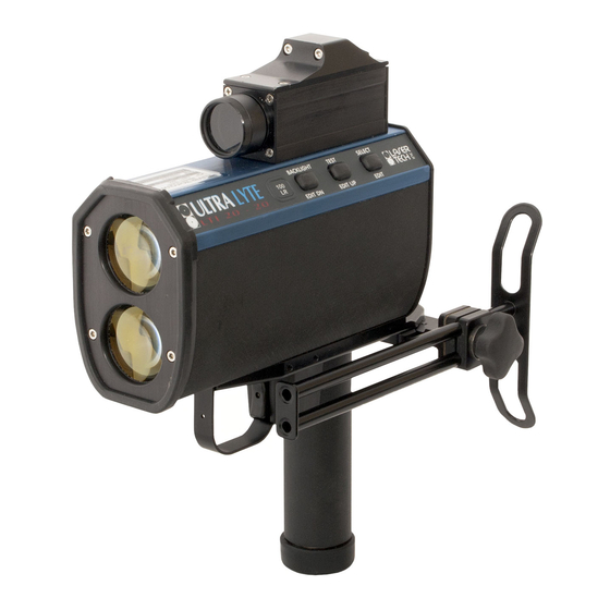
For Internal Use Only. Not for Distribution. Sighting scope Sensors Transmit lens Left Button panel The UltraLyte has two lenses on the front panel. The Fold-away stock top lens transmits infrared laser signals; the bottom (folded position) lens receives signals back from the target and feeds Receive lens signal information to the internal circuitry. -
Page 14: The Lcd Screen
NATOMY OF THE LTRA For Internal Use Only. Not for Distribution. absolute maximum is about 2000 feet (610 meters) for an UltraLyte, and 4000 feet (1200 meters for an UltraLyte LR. The tilt sensor on the Model 200 measures vertical SPEED angles, which the instrument uses to calculate height and elevation. -
Page 15: Serial Port Connector
• an in-scope, red aiming dot to help you aim accurately to the target • an in-scope measurement display In-scope Display Electronic Copy of LTI’s UltraLyte User’s Manual – 7 Edition June 1998... -
Page 16: Button Panels
ANELS For Internal Use Only. Not for Distribution. Button Panels The UltraLyte has two 3-button panels, one on each side of the instrument. The buttons give you access to instrument functions. The buttons have the following functions: Panel Button Location... -
Page 17: Inserting The Batteries
Warning: The UltraLyte is designed to accept normal C cells. NiCad batteries can be used, but they tend to vary in size. Laser Technology will not be responsible for damage that results from trying to force NiCad cells in or out of the battery Handle compartment. -
Page 18: Using The Stock
1. Loosen the stock by turning the tension knob Unfolding the Stock for Left-handed counter-clockwise. Operation 2. Rotate the stock 180 degrees. 3. Retighten the tension knob. Rotate Tighten Loosen Electronic Copy of LTI’s UltraLyte User’s Manual – 7 Edition June 1998... -
Page 19: Unfolding The Stock For Right-Handed Operation
3. Swivel the stock to the right until the retainer peg re-engages. When the peg engages, you hear a loud click. Retainer Plate Electronic Copy of LTI’s UltraLyte User’s Manual – 7 Edition June 1998... -
Page 20: Adjusting The Length And Angle
Usually it is instrument. best if the stock is at a slight downward angle. Length adjustment Angle adjustment Tighten Loosen Electronic Copy of LTI’s UltraLyte User’s Manual – 7 Edition June 1998... -
Page 21: Ttaching The Oke
For Internal Use Only. Not for Distribution. Attaching the Yoke Yoke Adapter The UltraLyte includes, as an option, a “yoke” that allows you to mount the instrument on a tripod or monopod. In order to attach the yoke, you must first assemble a “yoke adapter”... -
Page 22: Powering
That shows all the display segments so you can check that they are all operating. Power on by For more information, see “Testing Display squeezing the trigger Integrity,” later in this manual. Electronic Copy of LTI’s UltraLyte User’s Manual – 7 Edition June 1998... -
Page 23: Checking The Model Number
While still holding down the trigger, press and hold Backlight/Edit Dn until the message CLEAr appears on the display. That indicates that the factory default configuration has been restored. Electronic Copy of LTI’s UltraLyte User’s Manual – 7 Edition June 1998... -
Page 24: Screen
The table that begins on the next page lists and (You can extend that time by holding the trigger explains each indicator. pressed.) With every indicator showing, the screen looks like this: Electronic Copy of LTI’s UltraLyte User’s Manual – 7 Edition June 1998... -
Page 25: Indicators
CREEN NDICATORS For Internal Use Only. Not for Distribution. Note: Your UltraLyte instrument may not have all the features indicated in this table. Indicator Feature Indicated Explanation Display Backlight The display backlight is on. MENU Options menu You are in the instrument’s option menu. - Page 26 In TOD mode, the time (in seconds) the target took to travel the distance. D, G Inclination units Units for inclination measurements (UL200 only). D = degrees, G = gradients Power units Battery voltage indicator. Electronic Copy of LTI’s UltraLyte User’s Manual – 7 Edition June 1998...
-
Page 27: Menu
PTIONS For Internal Use Only. Not for Distribution. Menu Options The following table lists the options available through the Menu/Options button. Note: Your UltraLyte instrument may not have all the options listed. Option Screen Indicators Explanation Display Intensity Varies the in-scope display brightness. -
Page 28: Istening To The Nstrument
NSTRUMENT For Internal Use Only. Not for Distribution. Listening to the Instrument Sound Meaning The UltraLyte emits a variety of ticks and tones Single high-pitched The instrument succeeded in when it takes readings. The sounds vary depending tone taking the intended measurement. -
Page 29: Edit
For Internal Use Only. Not for Distribution. Once in edit mode, the instrument exhibits the Edit Mode following behavior: The UltraLyte has an editor that can be used to • Select/Edit selects the next digit to the right. If manually enter numeric values for various the right-most digit is already selected, exits edit instrument settings. -
Page 30: Speed Measurement
Or, if you press and hold the trigger down, the red dot will turn on and the instrument will begin a measurement about three-quarters of a second later. Electronic Copy of LTI’s UltraLyte User’s Manual – 7 Edition June 1998... -
Page 31: Measuring A Moving Vehicle
Measuring a Moving Vehicle As long as the trigger is kept pressed, your UltraLyte instrument may retry the speed measurement, To measure the velocity of a vehicle using the depending upon its configuration, up to 10 times or UltraLyte, use the following procedure: more. -
Page 32: Line Of Sight
The following If a target vehicle is moving directly toward or away table shows the effect: from you, the velocity measured by the UltraLyte is identical to the vehicle’s true speed. Electronic Copy of LTI’s UltraLyte User’s Manual – 7... - Page 33 The cosine effect decreases as the range to the target vehicle increases. At the maximum range of the instrument, the vehicle is so far away that the Electronic Copy of LTI’s UltraLyte User’s Manual – 7 Edition June 1998...
- Page 34 .9997 .9999 Remember that the cosine effect is always in the .9950 .8660 .9798 .9987 .9997 motorist's favor. .9950 .0000 .9165 .9798 .9987 .0000 .6000 .9165 .9798 .9950 Electronic Copy of LTI’s UltraLyte User’s Manual – 7 Edition June 1998...
-
Page 35: Time
3. Position yourself at a convenient spot where you between two reference points, and use the precise can clearly see both reference points. timing of the UltraLyte to measure how long it takes 4. Signal the instrument to start timing when the the vehicle to travel that distance. -
Page 36: Entering The Distance Manually
Speed/Options button the bottom display (right button panel) to area. SPEED invoke TOD mode. 3. Press and hold the Select/Edit button to invoke edit mode. SPEED Electronic Copy of LTI’s UltraLyte User’s Manual – 7 Edition June 1998... -
Page 37: Measuring The Distance
For example: path of traffic Decide which method you will use and, when you are properly positioned, follow this procedure: Electronic Copy of LTI’s UltraLyte User’s Manual – 7 Edition June 1998... - Page 38 Aim to the near points. reference point and press the trigger. The SPEED screen displays the distance. Press Select/Edit to go to the second distance display. SPEED Electronic Copy of LTI’s UltraLyte User’s Manual – 7 Edition June 1998...
-
Page 39: Taking The Measurements
SPEED When a vehicle passes one point, press the trigger to begin timing. SPEED When the vehicle passes the second point, press the trigger to stop. Electronic Copy of LTI’s UltraLyte User’s Manual – 7 Edition June 1998... -
Page 40: Notes On Using Tod
If you are measuring the distance with the • To set up for a different pair of reference points, UltraLyte, make sure you are directly in line with exit back to the main TOD screen by pressing both targets. the Select/Edit button. Then repeat the procedure for entering the distance. -
Page 41: Survey Measurements
Slope distance Measured Calculated The UltraLyte 100 has no way to measure angles, Inclination angle and takes only slope distance measurements. The UltraLyte 200, however, has a tilt sensor that allows it to measure inclination as well as slope distance. -
Page 42: In-Scope Display
Press the trigger to turn on the scope aiming display represents a survey dot, and sight the target measurement, not a speed. through the scope Press the trigger. SURVEY Electronic Copy of LTI’s UltraLyte User’s Manual – 7 Edition June 1998... -
Page 43: Grouping Sensors On A Ul200
When using the Group feature, you may find it helpful to first clear the sensors that you wish to group by quick-pressing the Select/Edit button in the desired menu. Electronic Copy of LTI’s UltraLyte User’s Manual – 7 Edition June 1998... -
Page 44: Error Conditions
Error codes display in the numeric display area. In speed mode, for example, errors show at the top of the screen: SPEED Electronic Copy of LTI’s UltraLyte User’s Manual – 7 Edition June 1998... -
Page 45: Error Codes
TOD timing error. The target was timed for display. The exact code is dependent upon the level less than 1 second. and nature of the RFI. Electronic Copy of LTI’s UltraLyte User’s Manual – 7 Edition June 1998... -
Page 46: I N - Scope Display Intensity
Return to speed or survey mode by pressing the appropriate button. Go to the next menu option by pressing Menu/Options. Electronic Copy of LTI’s UltraLyte User’s Manual – 7 Edition June 1998... -
Page 47: Gates And Gate Windows
(The minimum range is zero in survey mode, 50 feet (15 m) in speed mode). Electronic Copy of LTI’s UltraLyte User’s Manual – 7 Edition June 1998... -
Page 48: Setting A Gate Value
The maximum allowable value of the long gate is 2005 feet/612 meters (4003 feet/1220 meters for the UltraLyte LR). To measure the distance with the UltraLyte, aim to a target that marks the location of the gate and press the trigger. Then go to step 6. -
Page 49: Turning Off A Gate
Go to the next menu option by pressing Menu/Options. value. You can go back in later and turn the gate back on, and you will still have the same value settings as before. Electronic Copy of LTI’s UltraLyte User’s Manual – 7 Edition June 1998... -
Page 50: Measurement Units
Speed measurement units cannot be changed. indicator to M or F. Return to speed or survey mode by pressing the appropriate button. Go to the next menu option by pressing Menu/Options. Electronic Copy of LTI’s UltraLyte User’s Manual – 7 Edition June 1998... -
Page 51: Continuous Mode
Electronic Copy of LTI’s UltraLyte User’s Manual – 7 Edition June 1998... -
Page 52: Muting The Instrument
Go to the next menu option by measurement has completed, an indication similar to pressing Menu/Options. the high or low pitch tone in normal mode. Electronic Copy of LTI’s UltraLyte User’s Manual – 7 Edition June 1998... -
Page 53: Power Conservationi
Use care. Disabling the power-off interval prevents The instrument time-out, however, can be. the instrument from automatically shutting off; it must be manually turned off or the battery life will be greatly reduced. Electronic Copy of LTI’s UltraLyte User’s Manual – 7 Edition June 1998... -
Page 54: Etting
Go to the next menu option by pressing Menu/Options. In native mode, all messages are downloaded in UltraLyte native format. For specific information about available download formats, see Appendix Electronic Copy of LTI’s UltraLyte User’s Manual – 7 Edition June 1998... -
Page 55: Testing
Note that you may also test the back panel display screen displays: integrity at power on, by holding the trigger pressed. MENU LASER BATT SPEED TEST DELTA CONT MUTE SURVEY Electronic Copy of LTI’s UltraLyte User’s Manual – 7 Edition June 1998... -
Page 56: Alignment Test
(A telephone pole is an excellent choice.) Make sure there is nothing behind the target the instrument might detect, so you know without doubt that any change in pitch is due strictly to the target. Electronic Copy of LTI’s UltraLyte User’s Manual – 7 Edition June 1998... -
Page 57: Voltage Detection
2.0V the button If you fail to change the batteries and the voltage panels lock out. drops even further, the button panels lock out. Electronic Copy of LTI’s UltraLyte User’s Manual – 7 Edition June 1998... -
Page 58: Nstrument Confidence Heck
Regardless of which test you intend to perform, we the center of the aiming point.) also suggest a test area be permanently installed in a convenient location. Electronic Copy of LTI’s UltraLyte User’s Manual – 7 Edition June 1998... -
Page 59: Fixed Distance Check
The distance reading should be 174, 175, or 176. Electronic Copy of LTI’s UltraLyte User’s Manual – 7 Edition June 1998... -
Page 60: Delta Distance Check
150 feet to the distance difference, however, is calculated and second target. Mark that spot and install that target. displayed in tenths of feet or in hundredths of meters. Electronic Copy of LTI’s UltraLyte User’s Manual – 7 Edition June 1998... - Page 61 NSTRUMENT ONFIDENCE HECK For Internal Use Only. Not for Distribution. Action Result 4. Press Select/Edit. The screen displays “d2.” 1. Power on by pressing TEST DELTA the trigger. SPEED 5. Aim to the near target and press the trigger. 2. Press Test/Options The screen displays the repeatedly until the distance plus or minus...
-
Page 62: Aintenance
It will withstand a reasonable again soon, remove the batteries before storing drop shock. If you drop the instrument, however, check the scope alignment before using the instrument for measurement. Electronic Copy of LTI’s UltraLyte User’s Manual – 7 Edition June 1998... -
Page 63: Caring For The Scope
The instrument provides a method of verifying the display integrity. You can do that as described in “Powering On and Off’ and in “Testing Display Integrity,” earlier in this manual. Electronic Copy of LTI’s UltraLyte User’s Manual – 7 Edition June 1998... -
Page 64: Realigning The Scope
2.5mm and one 1.5mm. • A target at which to aim the instrument. • A highly stable base for the instrument. A tripod is recommended. Electronic Copy of LTI’s UltraLyte User’s Manual – 7 Edition June 1998... -
Page 65: Adjustment Screws
Once the adjustment screws are exposed, turn them with a 1.5mm Allen wrench to adjust the position of the scope aiming dot, as shown in the following illustration: Electronic Copy of LTI’s UltraLyte User’s Manual – 7 Edition June 1998... -
Page 66: Realignment Procedure
Use the alignment test procedure on page 46 to double check the alignment. If the instrument doesn’t pass, repeat the realignment procedure. 8. Secure the instrument. When the instrument passes the alignment test, replace the cover screws. Electronic Copy of LTI’s UltraLyte User’s Manual – 7 Edition June 1998... -
Page 67: Aligning The Tilt Sensor
COPE For Internal Use Only. Not for Distribution. Aligning the Tilt Sensor The UltraLyte tilt sensor cannot be realigned in the field. If you have problems with inclination measurements, contact Laser Technology, Inc. to arrange to return the instrument to the factory for realignment. -
Page 68: Specifications
Survey mode: ± 2” (5 cm) NEMA 6 To a white target at 150 ft. (45 m), Construction: All aluminum, extruded 1σ housing Range Resolution: 0.1 ft (0.01 m), Survey mode Electronic Copy of LTI’s UltraLyte User’s Manual – 7 Edition June 1998... - Page 69 APPENDIX A SERIAL INTERFACE SPECIFICATIONS For Internal Use Only. Not for Distribution. Electronic Copy of LTI’s UltraLyte User’s Manual – 7 Edition June 1998...
-
Page 71: Serial Interface Specifications
20/20 format software for the Criterion instrument family. Criterion format The 20/20 and Criterion formats are combined in a single menu selection. Electronic Copy of LTI’s UltraLyte User’s Manual – 7 Edition June 1998... -
Page 72: Format Parameters
Note that when the format is set to 20.20.Cr, formatid the baud rate changes from 4800 BPS in is the download format type (UL100 or survey mode to 9600 BPS in speed mode. UL200). Electronic Copy of LTI’s UltraLyte User’s Manual – 7 Edition June 1998... -
Page 73: Speed/Range Data Message Format
Legal values: M=Miles per hour K=Kilometers per hour Response: C=Centimeters per second $ID,UL100,1.70*22 runits specifies the range units. Legal values are F (feet) and M (meters). Electronic Copy of LTI’s UltraLyte User’s Manual – 7 Edition June 1998... -
Page 74: Survey Data Message Format
Example Speed/Range Messages English units: is inclination (null for a UL100). $SP,50,700.0,M,F*BF <null> Metric units: is a null field. $SP,80,213.4,K,M*B4 is horizontal distance (null for UL100). Electronic Copy of LTI’s UltraLyte User’s Manual – 7 Edition June 1998... -
Page 75: Criterion Download Format
When the serial format is set to 20.20.Cr, the is a carriage return. instrument accepts Criterion-format requests for the firmware version ID. The request message must be in the following format: Electronic Copy of LTI’s UltraLyte User’s Manual – 7 Edition June 1998... -
Page 76: Survey Data Message Format
$PLTIT,ID, model, versionid *csum<CR><LF> Example Version ID Messages where: Request: $PLTIT,RQ,ID $PLTIT,ID identifies the message Response: $PLTIT,ID,UL100,1.70*44 model indicates the UltraLyte model (UL100 or UL200) Electronic Copy of LTI’s UltraLyte User’s Manual – 7 Edition June 1998... - Page 77 Legal values are F (feet) or M (meters). checksum. The checksum is calculated by XORing all the characters between the dollar sign and the asterisk. Electronic Copy of LTI’s UltraLyte User’s Manual – 7 Edition June 1998...
-
Page 78: 20-20 Download Format
When the serial format is set to 20.20.Cr, the Inclination: 34.8 degrees instrument accepts 20/20- and Marksman-format requests for the firmware version ID. The format is as follows: ID<CR>[<LF>] Electronic Copy of LTI’s UltraLyte User’s Manual – 7 Edition June 1998... - Page 79 Electronic Copy of LTI’s UltraLyte User’s Manual – 7 Edition June 1998...
-
Page 80: Speed/Range Data Message Format
0000.0 to 9999.9, unsigned. <CR><LF> is a carriage return/line feed. Note that this format has no units indicators. The values are in the units in effect when the measurement was taken. Electronic Copy of LTI’s UltraLyte User’s Manual – 7 Edition June 1998...
Need help?
Do you have a question about the UltraLyte and is the answer not in the manual?
Questions and answers