Table of Contents
Advertisement
Quick Links
ESP8266 WiFi
The ESP8266 is the name of a micro controller designed by Espressif Systems. The
ESP8266 itself is a self-contained WiFi networking solution offering as a bridge from
existing micro controller to WiFi and is also capable of running self-contained applications.
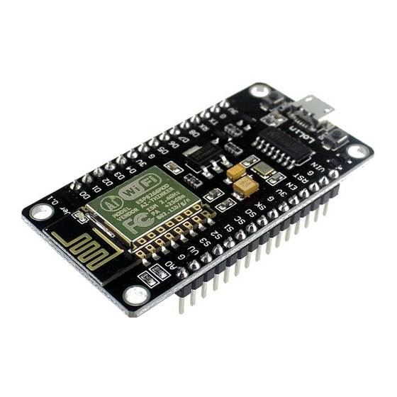
This module comes with a built in USB connector and a rich assortment of pin-outs. With a
micro USB cable, you can connect NodeMCU devkit to your laptop and flash it without any
trouble, just like Arduino. It is also immediately breadboard friendly.
1
www.handsontec.com
Advertisement
Table of Contents

Related Manuals for Handson Technology ESP8266 WiFi

Summary of Contents for Handson Technology ESP8266 WiFi
- Page 1 ESP8266 WiFi The ESP8266 is the name of a micro controller designed by Espressif Systems. The ESP8266 itself is a self-contained WiFi networking solution offering as a bridge from existing micro controller to WiFi and is also capable of running self-contained applications.
-
Page 2: Table Of Contents
Table of Contents Specification ............................3 Pin Definition ............................3 Using Arduino IDE ..........................3 Install the Arduino IDE 1.6.4 or greater ....................4 Install the ESP8266 Board Package ....................4 Setup ESP8266 Support ......................... 5 Blink Test ............................7 Connecting via WiFi ........................ -
Page 3: Specification
1. Specification: • Voltage:3.3V. • Wi-Fi Direct (P2P), soft-AP. • Current consumption: 10uA~170mA. • Flash memory attachable: 16MB max (512K normal). • Integrated TCP/IP protocol stack. • Processor: Tensilica L106 32-bit. • Processor speed: 80~160MHz. • RAM: 32K + 80K. •... -
Page 4: Install The Arduino Ide 1.6.4 Or Greater
The most basic way to use the ESP8266 module is to use serial commands, as the chip is basically a WiFi/Serial transceiver. However, this is not convenient. What we recommend is using the very cool Arduino ESP8266 project, which is a modified version of the Arduino IDE that you need to install on your computer. This makes it very convenient to use the ESP8266 chip as we will be using the well-known Arduino IDE. -
Page 5: Setup Esp8266 Support
Click ‘Tools’ -> ‘Board:’ -> ‘Board Manager…’ to access this panel. Scroll down to ‘ esp8266 by ESP8266 Community ’ and click “Install” button to install the ESP8266 library package. Once installation completed, close and re-open Arduino IDE for ESP8266 library to take effect. Setup ESP8266 Support When you've restarted Arduino IDE, select ‘Generic ESP8266 Module’... - Page 6 Select ‘115200’ baud upload speed is a good place to start - later on you can try higher speeds but 115200 is a good safe place to start. Go to your Windows ‘Device Manager’ to find out which Com Port ‘USB-Serial CH340’ is assigned to. Select the matching COM/serial port for your CH340 USB-Serial interface.
-
Page 7: Blink Test
Select the correct Com Port as indicated on ‘Device Manager” Find out which Com Port is assign for CH340 Note: if this is your first time using CH340 “ USB-to-Serial ” interface, please install the driver first before proceed the above Com Port setting. The CH340 driver can be download from the below site: https://github.com/nodemcu/nodemcu-devkit/tree/master/Drivers Blink Test We'll begin with the simple blink test. - Page 8 • When you release the ‘RST’ button, the blue indication will blink once, this means its ready to bootload. Once the ESP board is in bootload mode, upload the sketch via the IDE, Figure 3-2. Figure3-1: Connection diagram for the blinking test www.handsontec.com...
-
Page 9: Connecting Via Wifi
Figure 3.2: Uploading the sketch to ESP8266 NodeMCU module. The sketch will start immediately - you'll see the LED blinking. Hooray! Connecting via WiFi OK once you've got the LED blinking, let’s go straight to the fun part, connecting to a webserver. Create a new sketch with this code: Don’t forget to update: const char* ssid = "yourssid";... - Page 10 const char* host = "www.handsontec.com"; void setup() { Serial.begin(115200); delay(100); // We start by connecting to a WiFi network Serial.println(); Serial.println(); Serial.print("Connecting to "); Serial.println(ssid); WiFi.begin(ssid, password); while (WiFi.status() != WL_CONNECTED) { delay(500); Serial.print("."); Serial.println(""); Serial.println("WiFi connected"); Serial.println("IP address: "); Serial.println(WiFi.localIP());...
- Page 11 Open up the IDE serial console at 115200 baud to see the connection and webpage printout! That's it, pretty easy right ! This section is just to get you started and test out your module. www.handsontec.com...
-
Page 12: Flashing Nodemcu Firmware On The Esp8266 Using Windows
4. Flashing NodeMCU Firmware on the ESP8266 using Windows Why flashing your ESP8266 module with NodeMCU? NodeMCU is a firmware that allows you to program the ESP8266 modules with LUA script. And you’ll find it very similar to the way you program your Arduino. With just a few lines of code you can establish a WiFi connection, control the ESP8266 GPIOs, turning your ESP8266 into a web server and a lot more. -
Page 13: Wiring
Wiring: ESP8266 Pin Description CH_PD Pull high, connect to Vcc +3.3V Power Supply +3.3V Connect to RXD (white) of PL2303HX USB-Serial converter cable Connect to TXD (Green) of PL2303HX USB-Serial converter cable GPIO0 Pull low, connect to GND pin Power Supply ground Downloading NodeMCU Flasher for Windows After wiring your circuit, you have to download the NodeMCU flasher. - Page 14 Press the button “Flash” and it should start the flashing process immediately, showing the Module MAC address if successful connected. After finishing this flashing process, it should appear a green circle with a check icon at lower left corner. Your ESP8266 module is now loaded with NodeMCU firmware. www.handsontec.com...
-
Page 15: Getting Started With The Esplorer Ide
5. Getting Started with the ESPlorer IDE ESPlorer is an IDE (Integrated Development Environment) for ESP8266 devices. It’s a multi platform IDE, can be used in any OS environment, this simply means that it runs on Windows, Mac OS X or Linux. Supported platforms: •... - Page 16 Note: If you’re on Mac OS X or Linux you simply use this command line in your terminal to run the ESPlorer: sudo java –jar ESPlorer.jar. When the ESPlorer first opens, that’s what you should see: Here’s a rundown of the features the ESPlorer IDE includes: •...
- Page 17 In the top right corner you have all the options you need to establish a serial communication (you’re going to learn how to use them later in this Guide). This next screenshot shows your Code Window, that’s where you write your scripts (your scripts are highlighted with your code syntax).
-
Page 18: Schematics
Schematics To upload code to your ESP8266, you should connect your ESP8266 to your PL2303HX USB-UART Programming Cable like the figure below: Writing Your Lua Script Below is your script to blink an LED. lighton=0 pin=4 gpio.mode(pin,gpio.OUTPUT) tmr.alarm(1,2000,1,function() if lighton==0 then lighton=1 gpio.write(pin,gpio.HIGH) else... - Page 19 Having your ESP8266+PL2303HX Programmer connected to your computer, go to the ESPlorer IDE: Look at the top right corner of your ESPlorer IDE and follow these instructions: 1. Press the Refresh button. 2. Select the COM port for your FTDI programmer. 3.
- Page 20 Copy your Lua script to the code window (as you can see in the Figure below): The next step is to save your code to your ESP8266! At the left bottom corner click the button “Save to ESP”. In your output window, it should start showing exactly which commands are being sent to your ESP8266 and it should look similar to the Figure below.
- Page 21 Note: If you want to delete your “init.lua” file, you can do that easily. Simply type file.remove(“init.lua”) and press the button “Send” (see Figure above). Or you can type the command file.format() to remove all the files saved in your ESP8266.
-
Page 22: Nodemcu Gpio For Lua
6. NodeMCU GPIO for Lua The GPIO(General Purpose Input/Output) allows us to access to pins of ESP8266 , all the pins of ESP8266 accessed using the command GPIO, all the access is based on the I/O index number on the NoddMCU dev kits, not the internal GPIO pin, for example, the pin ‘D7’...
Need help?
Do you have a question about the ESP8266 WiFi and is the answer not in the manual?
Questions and answers