Table of Contents
Advertisement
Advertisement
Table of Contents

Related Manuals for Ridder MotorControl RMC400


Summary of Contents for Ridder MotorControl RMC400
- Page 1 Ridder Drive Systems B.V. Lorentzstraat 32 T +31 (0)341 416 854 3846 AX Harderwijk F +31 (0)341 416 611 PO Box 360 I ridder.com 3840 AJ Harderwijk E info@ridder.com the Netherlands Product Manual Ridder MotorControl RMC400 Original product-manual 265047EN - 2019.12 - V04...
-
Page 2: Table Of Contents
8. MAINTENANCE INSTRUCTIONS 8.1 Maintenance 9. SERVICE 9.1 Troubleshooting 9.2 Blink codes 9.3 Technical support 10. ENVIRONMENT 10.1 Decommissioning and removal 10.2 Waste disposal Ridder Drive Systems B.V. T +31 (0)341 416 854 - F +31 (0)341 416 611 - I ridder.com... -
Page 3: Guidelines, Standards And Conditions
• It is not permitted to use the RMC400 control-unit to lift or move people. Refer to §3.3 for a description of the intended use. 1.4 Warranty provisions For the warranty period and conditions refer to the ‘Conditions’ section on our website at ridder. com, or in the Ridder catalogue. Ridder Drive Systems B.V. -
Page 4: Safety, Precautions And Symbols
• Parts of the electrical or electronic installations are connected to dangerous electrical voltages. Work without professional competence or not obeyed warning instructions could cause injury and/or material damage. Ridder Drive Systems B.V. T +31 (0)341 416 854 - F +31 (0)341 416 611 - I ridder.com... - Page 5 • Ridder is not responsible for injury, material damage or consequential damage if accessories are used that Ridder did not make. TRANSPORT, STORAGE AND PACKAGING The conditions and instructions that follow are applicable. • Ambient temperature: -15 to +60 °C (+5 to +140 °F).
-
Page 6: Residual Risks
Persons can be in danger of life if they touch a system that is in operation. Forces Because of the forces in the systems (in which the control unit is installed), Ridder cannot be sure that there will be no injury to persons or damage to the system. 2.4 Symbols and abbreviations This section tells about used symbols and abbreviations in this manual. -
Page 7: Product Details
440-600: Mains voltage 440 V, 480 V or 600 V (3~). RMC400: General designation Ridder RMC400 control units. 1~ - 3~ = 1-phase and 3-phase 3~ = 3-phase Ridder Drive Systems B.V. T +31 (0)341 416 854 - F +31 (0)341 416 611 - I ridder.com... -
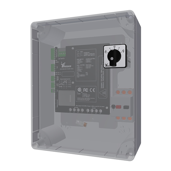
Page 8: Description
The protection rating of the RMC400 housing is IP54. Ridder Drive Systems B.V. T +31 (0)341 416 854 - F +31 (0)341 416 611 - I ridder.com... -
Page 9: Application
Weight 2.4 - 3.2 kg Ambient Protection rating IP54 Ambient temperature 0 to +60 °C (+32 to +140 °F) Maximum relative humidity Ridder Drive Systems B.V. T +31 (0)341 416 854 - F +31 (0)341 416 611 - I ridder.com... - Page 10 3~ 440-600 V, 10 FLA, 60 LRA Refer to the table that follows for abbreviations, technical specifications and descriptions of all connections. Ridder Drive Systems B.V. T +31 (0)341 416 854 - F +31 (0)341 416 611 - I ridder.com...
- Page 11 24 V DC RPU CALIBRATION A Output 0.5/1 mA RPU CALIBRATION B Output 24 V DC 0.5/1 mA Neutral wire Power supply Ridder Drive Systems B.V. T +31 (0)341 416 854 - F +31 (0)341 416 611 - I ridder.com...
-
Page 12: Install Instructions
RMC400 control-unit 272031 Cable gland M20\IP68\PA\LC 272033 Nut M20 PA NOTE: The installer must install the supplied cable glands and nuts as necessary. Ridder Drive Systems B.V. T +31 (0)341 416 854 - F +31 (0)341 416 611 - I ridder.com... -
Page 13: Special Tools And Equipment
• Make sure that no damage is caused to the gasket and that it does not become dirty. • Install the cover again after the work! Refer to the end of chapter 7. (4x) Slot ± 9x2 mm Ridder Drive Systems B.V. T +31 (0)341 416 854 - F +31 (0)341 416 611 - I ridder.com... -
Page 14: Connect Instructions
Use only applicable components and electrical material. Always refer to the related information and manuals. Ridder Drive Systems B.V. T +31 (0)341 416 854 - F +31 (0)341 416 611 - I ridder.com... -
Page 15: Protection - Conditions And Starting Points
Induction can have many causes such as: • Cable lengths • External sources • Too many cables together. Separation of cables is necessary. This prevents problems with induction. Ridder Drive Systems B.V. T +31 (0)341 416 854 - F +31 (0)341 416 611 - I ridder.com... -
Page 16: Overview And Function Diagram
5.3 Overview and function diagram The diagram that follows shows the RMC400 control-unit in a system. Ridder Drive Systems connects the components (if applicable) in the framework A1. Supply Voltage Supply Voltage 24 V AC/DC Control Temperature Control Board Fault Contact... - Page 17 CONTROL BOARD A2 (RCB) Position Feedback Limit Switch Thermal Protection Power In §5.11 OPTIONAL §5.8 §5.5/ §5.6/ §5.7 Manual Control §5.10 OPTIONAL Ridder Drive Systems B.V. T +31 (0)341 416 854 - F +31 (0)341 416 611 - I ridder.com...
-
Page 18: 3-Phase Electric Motor (208-600 Vac)
• Connect the supply voltage to the MPCB (if applicable) or X1 (MAINS), and PE (protective earth). (In) (Out) (In) Control board A2 6 x 1,5 mm² 4 x 1,5 mm² Ridder Drive Systems B.V. T +31 (0)341 416 854 - F +31 (0)341 416 611 - I ridder.com... -
Page 19: 1-Phase 3-Wire Electric Motor (115-230 Vac)
• Connect the supply voltage to the MPCB (if applicable) or X1 (MAINS), and PE (protective earth). (In) (Out) (In) Control board A2 6 x 1,5 mm² 3 x 1,5 mm² Ridder Drive Systems B.V. T +31 (0)341 416 854 - F +31 (0)341 416 611 - I ridder.com... -
Page 20: 1-Phase 5-Wire Electric Motor (115-230 Vac)
Connect a limit switch (RSU/RLS) to X9 of the control board (A2). Refer to the diagram that follows. Also refer to the product manual of the used Ridder motor-gearbox at ridder.com. Control board A2 Common Ridder Drive Systems B.V. T +31 (0)341 416 854 - F +31 (0)341 416 611 - I ridder.com... -
Page 21: Automatic Control (Acs) (24 V Ac/Dc)
• Connect the manual control (MC). Refer to the diagram that follows. Refer to the related manual when you connect a different manual control (MC). Control-board A2 Ridder Drive Systems B.V. T +31 (0)341 416 854 - F +31 (0)341 416 611 - I ridder.com... -
Page 22: Optional - Position Feedback (Rpu)
Go to step 4-A. Blink code is 2.2. The LED D3 (RPU CAL. B) comes on. Refer to §6.2 and §9.2. Go to step 4-B. Ridder Drive Systems B.V. T +31 (0)341 416 854 - F +31 (0)341 416 611 - I ridder.com... -
Page 23: Optional - Alarm (Al)
Obey the diagram that follows to connect the fault contacts (X5) to two or more control units. Alarm (AL) Control-board A2 Control-board A2 Control-board A2 Ridder Drive Systems B.V. T +31 (0)341 416 854 - F +31 (0)341 416 611 - I ridder.com... -
Page 24: User Instructions
D1 and D2 on the control board (A2). The control board (A2) and the manual control (MC) show the blink codes (D1 and D2) at the same time. OPTIONAL Green Ridder Drive Systems B.V. T +31 (0)341 416 854 - F +31 (0)341 416 611 - I ridder.com... -
Page 25: Operation
This section tells about the operating functions of the RMC400 control-unit: • With a built-in manual control (MC) and connected to an automatic control-system (ACS) • Without a built-in manual control (MC) and connected to a Ridder manual control (MC) (277950) and an automatic control-system (ACS). -
Page 26: Alarm
5. Error-message indication with four LEDs on the control board (A2). 6. Feedback of error messages with a fault contact. Ridder Drive Systems B.V. T +31 (0)341 416 854 - F +31 (0)341 416 611 - I ridder.com... -
Page 27: Commissioning Instructions
• §7.3 Check: Control direction of the Automatic Control (ACS) • §7.4 Check: Control direction of the Manual Control (MC). Refer to the product manual of the used Ridder motor-gearbox at ridder.com to adjust the end positions! Do not go across the limits of the system. This prevents damage or injury. -
Page 28: Check: Switching Sense Of The Limit Switch (Rsu/Rls)
3. Interchange the connections 2 and 3 of connector X9. Control-board A2 4. Energize the system. Go to step 1. 5. The check procedure of the switching sense is completed. Ridder Drive Systems B.V. T +31 (0)341 416 854 - F +31 (0)341 416 611 - I ridder.com... -
Page 29: Check: Control Direction Of The Automatic Control (Acs)
Control-board A2 5. Energize the system. Go to step 1. 6. The check procedure of the direction-of-rotation of the automatic control is completed. Ridder Drive Systems B.V. T +31 (0)341 416 854 - F +31 (0)341 416 611 - I ridder.com... -
Page 30: Check: Control Direction Of The Manual Control (Mc)
• Do a check of the gasket for dirt and damages. • Tighten the cover screws crosswise and gradually with the correct tightening torque. Slot ± 9x2 mm (4x) - 0.8 Nm Ridder Drive Systems B.V. T +31 (0)341 416 854 - F +31 (0)341 416 611 - I ridder.com... -
Page 31: Maintenance Instructions
• Replacement of parts is necessary • A problem is found with no solution. Refer to §9.1 first. Refer to the Ridder catalogue or the website at ridder.com for more information about spare parts (or accessories) that are available. 9. SERVICE If necessary remove covers to do the work. -
Page 32: Troubleshooting
A phase failure is detected. Solution 1 Make sure that all phases are connected correctly. Make sure that the connection terminals have a good connection. Ridder Drive Systems B.V. T +31 (0)341 416 854 - F +31 (0)341 416 611 - I ridder.com... -
Page 33: Blink Codes
Reference monitoring: Connect the reference input to connector 2 of X7. Reference monitoring: Connect the reference input to connector 3 of X7. Ridder Drive Systems B.V. T +31 (0)341 416 854 - F +31 (0)341 416 611 - I ridder.com... -
Page 34: Technical Support
4. Make the product unserviceable and make a mark on the product. This prevents that the product is (accidentally) used again. 5. The permanent decommissioning is completed. Refer to §10.2 “Waste disposal”. Ridder Drive Systems B.V. T +31 (0)341 416 854 - F +31 (0)341 416 611 - I ridder.com... -
Page 35: Waste Disposal
10.2 Waste disposal Discard products of Ridder Drive Systems after their lifespan and obey the applicable national and/ or local regulations. Make sure that after disassembly there is a separation of: • The collected operating materials (if applicable) such as oil, grease and such •...
Need help?
Do you have a question about the MotorControl RMC400 and is the answer not in the manual?
Questions and answers