Table of Contents
Advertisement
Quick Links
Advertisement
Table of Contents

Related Manuals for VPG VanWeigh


Summary of Contents for VPG VanWeigh
- Page 1 VanWeigh ® Installation, Setup and Calibration Manual vpgonboard.com...
- Page 2 ® VanWeigh...
-
Page 3: Important Installation Information And Liability Waiver
VPG does not accept responsibility for the structural integrity of the vehicle concerned, for any part thereof, and for its proper, safe operation. The company also reserves the right to make any amendments and alterations to this document deemed necessary. -
Page 4: Table Of Contents
Axle transducer on a front strut Span weights: Axle transducer on a leaf spring Appendix B Air pressure transducer VanWeigh display Molex Microfit 24- How to install a steel axle way connector transducer How to install an air pressure Appendix C... - Page 5 VanWeigh ®...
-
Page 6: Introduction And Scope
® VanWeigh Introduction and scope VanWeigh® is an overload monitoring system for use on twin axle vehicles with mechanical or air suspension systems. Scope This document is intended as a guide to the installation and commissioning of VanWeigh®. It covers two transducer types currently supported in a VanWeigh® system: VanWeigh®... -
Page 7: Important Installation Information
See “How to install a steel axle transducer” on page 27 • VanWeigh® axle transducer orientation. Axle transducers must be mounted to the vehicle in the correct orientation. See “How to install a steel axle transducer” on page 27 •... - Page 8 ® VanWeigh...
-
Page 9: Installation
VanWeigh ® Installation... -
Page 10: Components
VanWeigh Components Below is a list of components that can be used in a VanWeigh® installation. Check that you have all of the appropriate components for your installation before starting. Images are for illustration purposes only. Later versions may differ. - Page 11 VanWeigh ® Air Pressure Transducer The parts for the air pressure transducer are supplied in a bag. A single air transducer is made up from a T-connector, a brass sensor fitting and two plastic air pipe fittings This is supplied for air suspension...
- Page 12 ® VanWeigh Junction Box A single junction box is supplied for the rigid vehicle Part No: 341410 Internal Domain Junction Box Cable 3 way The cable is identified by the green junction box connector and 3 male internal domain cable...
- Page 13 VanWeigh ® External Domain/Power cable A single external domain cable is supplied for the system The cable is identified by the external domain cable connector at one end and the display connector at the other Part No: DRG-106143 Cable Protector and Cable Ties...
-
Page 14: Tools
® VanWeigh Tools Check that you have the following tools before starting an installation. Tool Check Screwdriver set Hex driver set Torx driver set Socket set Multimeter Side cutters Drill set G-Clamp Spanner set (including 18 mm and 24 mm) -
Page 15: Installation Overview
Ensure the engine of the vehicle is off and the parking brake is applied before starting the installation It is recommended that you use a mechanics pit inside a workshop to install the VanWeigh® system The VanWeigh® display unit is used to display sensor information once the system has been installed, configured and calibrated. - Page 16 ® VanWeigh There are three main steps to installing the VanWeigh® system: • Install the display unit. The display unit must be installed in the cab of the vehicle and connected to the vehicles power supply. The external domain cable must be routed from the display unit to the junction box.
-
Page 17: Typical System Schematics
VanWeigh ® Typical system schematics Below are two examples of system schematics showing where the junction box and transducers are fitted in relation to the vehicle. These are two example schematics, but a variety of configurations may be used. Leaf Spring Leaf Spring VanWeigh®... -
Page 18: How To Install The Display Unit
® VanWeigh How to install the display unit A single display unit is installed in the cab of the vehicle to display the sensor information. The display unit has a single port that connects to both the power supply on the vehicle and the junction box, via the external domain cable. - Page 19 Connect the white wire to the ignition to power the monitor on and off when the ignition is • PROJECT NAME: turned on or off VanWeigh 2 5. Plug the display unit cable into the rear of the display unit DATE: TITLE: No.
-
Page 20: How To Install The Junction Box
2. Mount the junction box to the vehicle: • The cable sockets must point to the rear of the vehicle The VanWeigh® system will not provide the correct measurements if the junction box is not mounted with the cable sockets pointing to the rear of the vehicle •... -
Page 21: Connecting The Cables
VanWeigh ® Connecting the cables The junction box has two ports. These are colour coded to ensure that only the correct cables can be connected to the correct port: Port with green tab. This is the connection for the first three sensors. Sensor information is •... -
Page 22: Sensor Types
® VanWeigh Sensor types Install the appropriate type of sensors on the suspension system of each wheel. There are two types of sensor: • Axle transducer. This type of sensor can be mounted on steel axle suspension systems. This includes: •... -
Page 23: Sensor Installation Positions
VanWeigh ® Sensor installation positions The first step to sensor installation is to select the appropriate position to install each type of sensor on the vehicle. Each sensor has a serial number. Make a note of the serial number of each sensor which you install, its position number and where it is installed on the vehicle. -
Page 24: Axle Transducer On A Front Strut
® VanWeigh Axle transducer on a front strut Select a position to install the transducer on a front strut where: • The transducer is perpendicular to the orientation of the chassis with the cable running away from the wheel •... -
Page 25: Axle Transducer On A Leaf Spring
VanWeigh ® Axle transducer on a leaf spring Select a position to install the transducer on a single axle leaf spring where: • The transducer is mounted to the top side of the spring • The transducer is parallel to the orientation of the chassis •... -
Page 26: Air Pressure Transducer
® VanWeigh Air pressure transducer Select a position to install the transducer in an air circuit where: • The transducer is between the self levelling valve and the air bellows • The air transducer can be supported without risk of damage from any moving parts •... -
Page 27: How To Install A Steel Axle Transducer
VanWeigh ® How to install a steel axle transducer A single axle transducer is used to monitor one side of an axle. In most cases, two axle transducers will be installed per axle, one on the suspension for the left wheel, one on the right. - Page 28 ® VanWeigh 4. Mount the sensor to the suspension and clamp in place for a minimum of 10 minutes 5. Connect the cable to the junction box • Ensure that cable to cable connections are well supported • Avoid running cables on or near sharp objects •...
-
Page 29: How To Install An Air Pressure Transducer
VanWeigh ® How to install an air pressure transducer A single air pressure transducer is used to monitor a single air Truck Air System circuit in an air suspension system. For example; a single air circuit with one ride height control valve that controls multiple bellows on both sides of the vehicle would require a single air pressure transducer. - Page 30 ® VanWeigh 1. Build the air pressure transducer: i. Disconnect the fitting from the sensor cable ii. Place the washer over the thread. It is recommended that PTFE tape is also applied iii. Connect the sensor to the fitting. Use 18 mm and 24 mm spanners to tighten iv.
- Page 31 VanWeigh ® 2. Depressurise the air suspension systems Ensure the air pressure system is fully depressurised to avoid movement in the suspension when the air pipe is cut 3. Reconnect the sensor to the cable It is recommended that self amalgamating tape is wrapped...
- Page 32 ® VanWeigh 9. Secure air pipe, transducer and cable to vehicle • Use cable ties to support air pipe and sensor cable connections. Secure the connectors to existing cables where possible • Ensure that cable to cable connections are well supported •...
-
Page 33: System Overview
VanWeigh ® System Overview... -
Page 34: Vanweigh® Display Unit Overview
® VanWeigh VanWeigh® Display Unit Overview The display unit is used to display the weight measurements from the sensors on the vehicle. The display unit must be configured to display any values in the appropriate format and allow any external devices to operate. See “How to configure the display” on page 54 and “” on page 55 The display unit will not display any weight measurements until the system has been: Configured to reflect the setup of the sensors and junction boxes on the vehicle. -
Page 35: Display Unit Operation
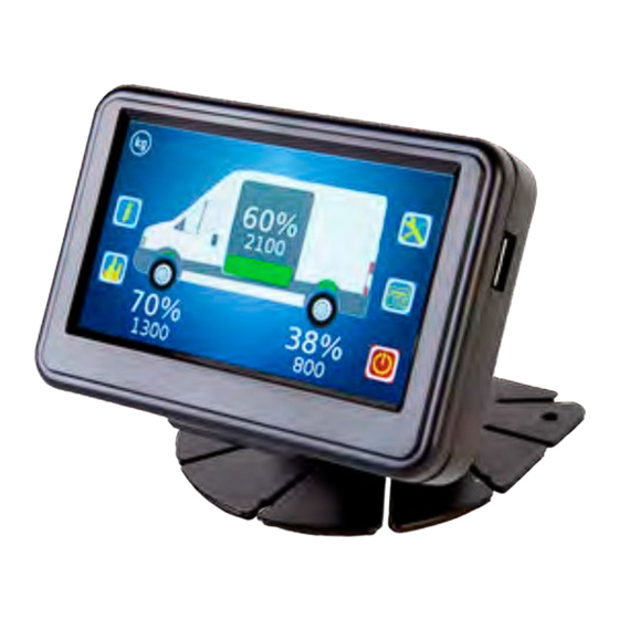
VanWeigh ® Display unit operation The display unit is automatically powered on by the ignition. It uses touch screen technology to operate it. Tap the screen to switch the screen on if it is in standby mode. Home Page The home page is displayed when the display unit is activated. This shows: •... -
Page 36: How To Navigate The System
® VanWeigh How to navigate the system Tap the home page screen to show the menu options: 2240 1460 There are five home page menu options: Configuration System info Diagnostics Standby - Tap to switch the display unit Tap a menu option to open its associated page:... -
Page 37: Editing Values
VanWeigh ® There are additional options on each page: Tap to return to the previous page Tap to retun to the home page Indicates the number of screens in Underlined text indicates another menu xxxx this page. Swipe up or down to show or an editable value. - Page 38 ® VanWeigh Sliders: Display Configuration Brightness Language English Tap the + or - icons to adjust the value up or down. Keypad: Cal. Span Weight Axle Calibration Axle 1 Span Weight 1700 Axle 2 Span Weight 2000 Do Span Tap to enter the numerical value and tap the return button to set the value...
-
Page 39: Configuration
VanWeigh ® Configuration 2240... -
Page 40: The Configuration Menu
There are six submenus in the configuration screen: • Login. Use this option to login to the VanWeigh® system. This will allow you to edit the configuration options. Vehicle Configuration. Use this menu to input the vehicle configuration into the VanWeigh®... -
Page 41: Login
VanWeigh ® Login Login to the VanWeigh® system to configure the system. 1. Tap the configuration icon in the home page to open the configuration menu 2. Tap login to display the keypad Please Enter PIN Login 3. Tap to enter the Engineer PIN number 4. -
Page 42: Vehicle Configuration
® VanWeigh Vehicle configuration 1. Tap the configuration icon on the home page to open the configuration menu 2. Tap Vehicle Configuration to open the vehicle configuration menu: Vehicle Configuration Junction Box 1 - 1 JBox Config Alarms Calibration The vehicle configuration is a step by step process that allows you to configure the junction box and alarms and finally calibrate the system. -
Page 43: How To Configure The Junction Box
VanWeigh ® How to configure the junction box The junction box is configured in the the vehicle configuration menu. From the home page, go to: Configuration > Vehicle Configuration. 1. Tap JBox Config to open the junction box setup menu:... - Page 44 ® VanWeigh 6. Tap Axles. A message box is displayed saying ‘Settings have changed - Send to Jbox (Yes) - Dicard changes (No)’. 7. Tap Yes to update. The axle set up menu is displayed: Axle Set Up Axle Number...
- Page 45 VanWeigh ® 14. Tap Sensors to open the sensor set up page: Sensor Set Up Serial Number xxxxx (xxxxxxxxxx) Position Direction Backwards Sensor 1 - 3 15. Swipe left or right to select a sensor to configure 16. Tap the Position value to set the position of the sensor The position number is the position of the sensor on the vehicle.
- Page 46 ® VanWeigh 19. Tap the back icon. A message box is displayed saying ‘Update Config-Send Sensor Map to Jbox?’ 20. Tap Yes to update and return to junction box setup page: Junction Box Set Up Junction Box Set Up Junction Box...
-
Page 47: How To Configure The Alarms
VanWeigh ® How to configure the alarms The alarms are configured in the the vehicle configuration menu. From the home page, go to: Configuration > Vehicle Configuration. Obtain the maximum allowable gross and axle weights from the vehicle data plate 1. -
Page 48: Weighing The Vehicle
Turn the display unit off and back on if you set the alarms after the calibration is complete. Weighing the Vehicle Once the VanWeigh® system has been configured, it must be calibrated. This requires multiple weight measurements of the axles on the vehicle. - Page 49 VanWeigh ® Weigh pads: 1. Use one pair of weigh pads per axle. If possible, weigh all axle at the same time. If not, use levelling mats to maintain the overall level of any axles which are not being weighed.
- Page 50 ® VanWeigh 5. Subtract the weight of the front axle from the weight of both axles to find the weight of the second axle Repeat steps 3 - 5 if there are more than 2 axles on the vehicle until all axles have been...
-
Page 51: How To Calibrate The Junction Box
VanWeigh ® How to calibrate the junction box Use the display unit installed in the cab to calibrate the VanWeigh® system after it has been configured. 1. Tap the configuration icon in the home page to open the configuration menu 2. - Page 52 ® VanWeigh 5. Tap Axle Zero to open the axle calibration menu Axle Calibration Axle 1 Zero Weight 1200 Axle 2 Zero Weight Do Zero Make sure the vehicle is empty before starting the zero calibration 6. Tap the Axle 1 Zero Weight value to set the zero weight for the first axle 7.
- Page 53 VanWeigh ® 12. Tap Axle Span to open the axle calibration menu Axle Calibration Axle 1 Span Weight 1700 Axle 2 Span Weight 2000 Do Span Make sure the vehicle is at GVW before starting the span calibration 13. Tap the Axle 1 Span Weight value to set the span weight for the first axle 14.
-
Page 54: How To Configure The Display
® VanWeigh How to configure the display 1. Tap the configuration icon in the home page to open the configuration menu 2. Tap Display to open the display configuration menu: Display Configuration Display Configuration Brightness Settings Language English 3. Tap the + or - button on the Brightness slider to increase or decrease the brightness setting 4. - Page 55 VanWeigh ® 6. Tap the + or - button on the Volume slider to increase or decrease the volume setting 7. Tap Date/Time to set the date and time 8. Tap the Power Off Time value to set the delay time before the display unit will power off 9.
-
Page 56: How To Configure A Serial Output
® VanWeigh How to configure a serial output Printer configuration is currently not available. 1. Tap the configuration icon in the home page to open the configuration menu 2. Tap System Config to open the system config menu: System Config... -
Page 57: How To Configure The Weighing Units
VanWeigh ® 5. Tap the Port Mode value to set the port mode: • Select Serial Data for serial output. Input the Baud Rate, Scoreboard Format, Transmit Period, Acknowledgement Required and Retries values • Select Printer for a printer output. Input the Baud Rate, Handshake and Print Options values 6. -
Page 58: How To Configure The Pin Numbers
® VanWeigh How to configure the PIN Numbers 1. Tap the configuration icon in the home page to open the configuration menu 2. Tap PIN Management to open the PIN management menu: PIN Management Fleet Manager Engineer Restore Defaults 3. Tap the PIN number you want to change 4. -
Page 59: System Info And Diagnostics
VanWeigh ® System info and Diagnostics... -
Page 60: System Info
® VanWeigh System Info Tap the system info icon in the home page to open the system info menu: System Info Vehicle Display Junction Box Count Messages There are four submenus in the system info page: • Vehicle. Use this menu to view information about the vehicle:... - Page 61 VanWeigh ® • Display. Use this menu to view information about the VanWeigh® display unit: Display Info Display Info Application Version: xx.xx.xx.xx Display Model VPGxxxx-xxxxxx Serial Number: xxxxxxx Bootloader Version: xx.xx.xx.xx Hardware Version: xx.xx • Junction Box Count. Use this menu to view information about the junction box and its sensors:...
- Page 62 ® VanWeigh • Messages. Use this menu to view any system messages: Messages No Messages Available Sounder Enabled...
-
Page 63: Diagnostics
VanWeigh ® Diagnostics Tap the diagnostics icon in the home page to open the diagnostics menu: Diagnostics Diagnostics Calibration Alarms View Logs Live View Voltages & Temperature There are five submenus in the diagnostics page: • Junction Box Calibration. Use this menu to view information about the junction box calibration,... - Page 64 ® VanWeigh Axle Calibration Axle Number 1 - 2 Cal. Zero Weight 1200 Cal. Span Weight 1700 Sensor Calibration Sensor Calibration Sensor Position Sensor Position Cal. Zero Weight Reading at Span 0.55449 Cal. Span Weight Reference at Zero Reading at Zero 0.255124...
- Page 65 VanWeigh ® • View Logs. Use this menu to View, Clear and Save the logs: View Logs Junction Box 1 - 1 View Logs Clear Logs Save Logs You must log in to clear logs. See “Login” on page 41 for guidance.
- Page 66 ® VanWeigh • Voltages and Temperature. Use this menu to view the current voltage and temperature data: Voltages & Temperature Input Voltage 23.5 V Output Voltage 23.1 V Temperature 57.7° Ignition Sense • Alarms. Use this menu to view the junction box and axle alarm settings:...
- Page 67 VanWeigh ® Appendix A...
-
Page 68: System Configuration Table
® VanWeigh System configuration table Junction box:_________________________________________________ Orientation:__________________________________________________ Axle Sensors Vehicle Left Side Vehicle Right Side It is recommended that you photocopy this table and use it to record the details of the sensors on your vehicle. If a single sensor used to monitor both sides of an axle, enter its details in the vehicle left side... -
Page 69: Zero And Span Weights Tables
VanWeigh ® Zero and span weights tables Zero weights: Axle Weight Weighbridge Measurements Weight Calculation Axle 1 = a Axle 2 = b - a Span weights: Axle Weight Weight Calculation Weighbridge Measurements Axle 1 = a Axle 2 = b - a... - Page 70 ® VanWeigh...
- Page 71 VanWeigh ® Appendix B...
-
Page 72: Vanweigh Display Molex Microfit 24-Way Connector
® VanWeigh VanWeigh display Molex Microfit 24-way connector Molex Microfit 24-Way connector view from front Function Description RS232_1_RTS RS232_1 Request to send - handshake RS232_1_CTS RS232_1 Clear to send - handshake V_OUT Output voltage to junction box Ground to junction box... - Page 73 VanWeigh ® Appendix C...
-
Page 74: Vanweigh Ii Specification
® VanWeigh VanWeigh II Specification Axle overload protection for light commercial vehicles with a GVW of up to 7.5t (RoW), 16535lbs (US) PARAMETRS MINIMUM TYPICAL MAXIMUM UNIT SYSTEM Accuracy Better than 2.5% 90 - 110% of Full scale Capacity (GVW) Up to 7.5... - Page 75 VanWeigh ® PARAMETRS MINIMUM TYPICAL MAXIMUM UNIT On screen kg/lb. display of weight Overload alarm- audible ≥85 Alarm output level dB(A) (at 24VDC) Password 4 digits, engineer and manager PIN protection Load deliver capability TRANSDUCERS Transducer types Up to 4 axle/air transducers...
- Page 76 ® VanWeigh...
- Page 77 VanWeigh ® Appendix D...
-
Page 78: Warning And Status Messages
® VanWeigh Warning and Status Messages WARNING / MESSAGE DESCRIPTION This is the first message the screen displays in Initialising… the power on sequence. Waiting for Junction boxes… The system is searching for the junction box during the power on sequence. - Page 79 VanWeigh ® WARNING / MESSAGE DESCRIPTION System unable to find all configured sensors. Warning Sensor Missing! icon for more information. Check connections. Note: System will continue to function, once message has been displayed, using the missing sensor’s last weight reading.
-
Page 80: Alarm / Warning Icons
® VanWeigh Alarm / Warning Icons ALARM / WARNING ICON DESCRIPTION Warning Message icon Tap icon for more information Alarm Sounding icon Tap icon to mute alarm sounder Alarm Muted Tap icon to unmute alarm sounder... -
Page 81: Message/Log Error Code Text
VanWeigh ® Message/Log Error Code Text MESSAGE / LOG ERROR TEXT DESCRIPTION Gross Overload Alarm triggered when the gross weight value exceeds the set alarm value Axle Overload Alarm triggered when the axle weight value exceeds the set alarm value... - Page 82 You should ensure you have the current version of the relevant information by contacting VPG prior to performing installation or use of the product, such as on our website at vpgsensors.com. No license, express, implied, or otherwise, to any intellectual property rights is granted by this document, or by any conduct of VPG.
Need help?
Do you have a question about the VanWeigh and is the answer not in the manual?
Questions and answers