
Related Manuals for HBM VKK2R-8 DIGITAL

Summary of Contents for HBM VKK2R-8 DIGITAL
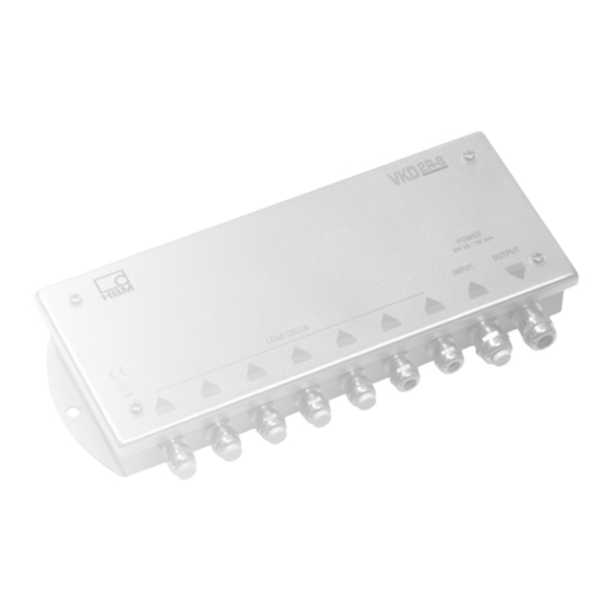
- Page 1 Mounting instructions Montageanleitung Junction box Klemmenkasten VKK2R-8 DIGITAL, VKD2R-8 VKK2R-8 DIGITAL VKD2R-8 A1144-3.0 en/de...
-
Page 2: Table Of Contents
VKK2R-8 DIGITAL, VKD2R-8 Contents Page Safety instructions .......... -
Page 3: Safety Instructions
Instructions and in particular the technical safety instructions. Symbol: Meaning: CE mark The CE mark enables the manufacturer to guarantee that the product complies with the requirements of the relevant EC guidelines. Please find the Declaration of Conformity under www.hbm.com. A1144-3.0 en/de/fr... - Page 4 VKK2R-8 DIGITAL, VKD2R-8 Remaining dangers The scope of supply and list of components provided with the junction box cover only part of the scope of connection technique. In addition, equipment planners, installers and operators should plan, implement and respond to the safety engineering considerations of connection technique in such a way as to minimize remaining dangers.
- Page 5 VKK2R-8 DIGITAL, VKD2R-8 NOTE Neither the design of the device nor any technical safety aspects may be modified without the express permission of Hottinger Baldwin Messtechnik GmbH. Any modification excludes Hottinger Baldwin Messtechnik GmbH from any and all liability for any damage resulting therefrom.
-
Page 6: Introduction And Appropriate Use
The VK... junction box is used to interconnect the serial interfaces (RS-485), the power supply and the RS-485 bus termination. It is preferable for the following HBM products to be wired in the RS-485 bus: • Digital transducers: C16i, FIT •... -
Page 7: Mechanical Construction
VKK2R-8 DIGITAL, VKD2R-8 Mechanical construction The junction box has the following functions: • Mechanical protection (IP65) • Power supply for the electrical bus termination • Transducer excitation • Bus operation for 2-wire and 4-wire RS-485 serial interfaces • EMC-tested The connection cable exits the casing via screw connections. -
Page 8: Mounting
VKK2R-8 DIGITAL, VKD2R-8 2.1 Mounting The VK... junction boxes should preferably be mounted such that the cable bushings point downward (see mounting direction, fig. 2). In this way, better protection against ingress of water is provided. (100) (250) (110) (260) (128) ∅... -
Page 9: Electrical Connection
VKK2R-8 DIGITAL, VKD2R-8 Electrical connection A connection diagram is attached to the lid of the VK..When making the connections, please ensure that the cable wires do not protrude beyond the connection clamps (risk of looping). Make sure that the cable screen is properly connected to the screw connections. -
Page 10: Clamp Connection
VKK2R-8 DIGITAL, VKD2R-8 3.2 Clamp connection All nine of the connection blocks in the VK... are interconnected in series. The VK... also contains terminating resistors that can be brought into circuit for the RS-485 bus. Each clamp has the following connections: VK...-Connection... -
Page 11: Power Supply
VKK2R-8 DIGITAL, VKD2R-8 3.3 Power supply The power supply complies with the operating voltage of the digital transducers / measuring amplifiers connected in the particular case. The relevant Operating Manual should be consulted for this. Product Operating voltage range [V C16i 6...15... - Page 12 The cable screen must not be used for this equipotential bonding. For EMC reasons, it is advisable to use a double-screened cable (from the HBM program, for example: 3 x 2 x 0.14 m 4-3301.0071).
-
Page 13: Rs-485 4-Wire Bus
(see Figure 8). The interface converter from HBM basically has bus terminating resistors that are ON. When using several VK...s, it is then only necessary to activate the bus termination in one VK..It is essential for the bus terminations integrated in the digital transducers / measuring amplifiers to be deactivated (factory setting). -
Page 14: Rs-485 2-Wire Bus
VKK2R-8 DIGITAL, VKD2R-8 3.6 RS-485 2-wire bus Using the RS-485 interface, several digital transducers / measuring amplifiers can be connected to a common bus line. Figure 7 shows the principle of bus cabling for 2-wire operation. VK... connection RS-485 2-wire... - Page 15 VK... contain the terminating resistors. In this VK..., the terminating resistors must be switched on (switch setting at the bus connection ON). The interface converter from HBM basically has bus terminating resistors that are ON. When using several VK...s, it is then only necessary to activate the bus termination in one VK..
-
Page 16: Connecting Vkd2R-8 With Dis2116
VKK2R-8 DIGITAL, VKD2R-8 3.7 Connecting VKD2R-8 with DIS2116 VK... RS-485 4-wire VK... DIS2116 (Clamp (input, Si- (output) gnals from C16i) screen connection Screen RS-485, transmitting line A (=T−) 1.7 (RA) RS-485, transmitting line B (=T+) 1.6 (RB) RS-485, receiving line A (=R−) 1.5 (TA) - Page 17 VKK2R-8 DIGITAL, VKD2R-8 VK... Specifications Type VK... RS-485 / RS-422 x 1000 Cable length (entire bus) HBM products to connect 4-wire bus 2-wire bus Digital transducers C16i, FIT AED9101B, Digital transducer electronics AED9201A AED9101B Digital meas.chains with transducer electronics AD104-R5...
- Page 18 VKK2R-8 DIGITAL, VKD2R-8 Inhalt Seite Sicherheitshinweise ..........
-
Page 19: Sicherheitshinweise
Klemmenkastens beauftragt ist, muß die Montageanleitung und insbe- sondere die sicherheitstechnischen Hinweise gelesen und verstanden haben. Symbol: Bedeutung: CE-Kennzeichnung Mit der CE-Kennzeichnung garantiert der Hersteller, daß sein Produkt den An- forderungen der relevanten EG-Richtlinien entspricht. Die Konformitätserklä- rung finden Sie unter www.hbm.com. A1144-3.0 en/de... - Page 20 VKK2R-8 DIGITAL, VKD2R-8 Restgefahren Der Leistungs- und Lieferumfang des Klemmenkastens deckt nur einen Teil- bereich der Anschlußtechnik ab. Sicherheitstechnische Belange der An- schlußtechnik sind zusätzlich vom Anlagenplaner/Ausrüster/Betreiber so zu planen, zu realisieren und zu verantworten, daß Restgefahren minimiert wer- den. Jeweils existierende Vorschriften sind zu beachten. Auf Restgefahren im Zusammenhang mit der Anschlußtechnik ist hinzuweisen.
- Page 21 VKK2R-8 DIGITAL, VKD2R-8 HINWEIS Das Gerät darf ohne ausdrückliche Zustimmung von der Hottinger Baldwin Messtechnik GmbH weder konstruktiv noch sicherheitstechnisch verändert werden. Jede Veränderung schließt eine Haftung seitens der Hottinger Bald- win Messtechnik GmbH für daraus resultierende Schäden aus. Jegliche Reparaturen, Lötarbeiten an den Platinen sowie ein Austauschen von Bauteilen ist strengstens untersagt.
-
Page 22: Einleitung Und Bestimmungsgemäße Verwendung
Einleitung und bestimmungsgemäße Verwendung Der Klemmenkasten VK... dient der Zusammenschaltung der seriellen Schnittstellen (RS-485), der Spannungsversorgung sowie dem RS-485-Bu- sabschluß. Vorzugsweise werden damit die folgenden Produkte von HBM im RS-485-Bus verdrahtet: • Digitale Aufnehmer: C16i, FIT • Digitale Aufnehmer-Elektroniken: AED9101B, AED9201A •... -
Page 23: Mechanischer Aufbau
VKK2R-8 DIGITAL, VKD2R-8 Mechanischer Aufbau Der Klemmenkasten bietet die folgenden Funktionen: • Mechanischen Schutz (IP65) • Spannungsversorgung für den elektrischen Busabschluss • Aufnehmerspeisung • Busbetrieb für die serielle Schnittstellen RS-485-2-Draht, RS-485-4-Draht • EMV-geprüft Die Anschlusskabel werden über Verschraubungen am Gehäuse herausge- führt. -
Page 24: Montage
VKK2R-8 DIGITAL, VKD2R-8 2.1 Montage Die Klemmenkästen VK... werden vorzugsweise so montiert, dass die Kabel- durchführungen nach unten weisen (siehe Montagerichtung, Abb. 2). Damit wird der Schutz gegen eindringende Feuchtigkeit erhöht. (100) (250) (110) (260) (128) Montagerichtung ∅ 7 7x M12, SW 14 für 2x M16, SW 17 für... -
Page 25: Elektrischer Anschluss
VKK2R-8 DIGITAL, VKD2R-8 Elektrischer Anschluss Im Deckel des VK... ist ein Anschlussschema eingeklebt. Bitte beachten Sie beim Anschließen, dass die Kabeladern nicht über die Anschluss-Klemmen herausragen (Gefahr von Schleifenbildung). Achten Sie bitte auch auf den korrekten Anschluss des Kabelschirms an die Verschraubung. -
Page 26: Klemmenanschluss
VKK2R-8 DIGITAL, VKD2R-8 3.2 Klemmenanschluss Alle neun Klemmenblöcke im VK... sind in Serie miteinander verbunden. Der VK... enthält zusätzlich zuschaltbare Abschlusswiderstände für den RS-485-Bus. Jede Klemme hat die folgenden Anschlüsse: VK...-Anschluß Bedeutung Screen Schirmanschluss RS-485, Sendeleitung A (= T−) RS-485, Sendeleitung B (= T+) RS-485, Empfangsleitung A (= R−) -
Page 27: Spannungsversorgung
Der Klemmenkasten kann für zwei Interfacevarianten (RS-485 2- / 4-Draht ) verdrahtet werden. Zum Anschluss der digitalen Aufnehmer / Messverstärker an den COM-Port eines PC’s (RS-232) ist ein Schnittstellenkonverter (von HBM: 1-SC232/422B) notwendig. Prinzipiell sollten für die Interfaceverdrahtung geschirmte Kabel verwendet werden, wobei der Kabelschirm über die Verschraubungen mit dem VK...-Ge-... - Page 28 Busteilnehmern hergestellt werden. Für diesen Potentialausgleich darf der Leitungsschirm nicht verwendet werden. Für die Leitung empfiehlt sich aus EMV-Gründen eine doppelt geschirmte Leitung (im HBM-Programm, z. B.: 3 x 2 x 0,14 m , 4-3301.0071). Schnittstellen-Konverter 1-SC232/422B...
-
Page 29: Rs-485-4-Draht-Bus
Waagenelektronik DIS2116 (siehe Abb. 8). Der Schnittstellenkonver- ter von HBM hat prinzipiell eingeschaltete Busabschlusswiderstände. Bei Ver- wendung von mehreren VK... ist dann nur in einem VK... der Busabschluss zu aktivieren. Die in den digitalen Aufnehmern / Messverstärkern eingebauten Busabschlüsse müssen unbedingt deaktiviert werden (Werkseinstellung). -
Page 30: Rs-485-2-Draht-Bus
VKK2R-8 DIGITAL, VKD2R-8 3.6 RS-485-2-Draht-Bus Über die Schnittstelle RS-485 können mehrere digitalen Aufnehmer / Mess- verstärker an eine gemeinsame Busleitung angeschlossen werden. Das Prin- zip der Busverkabelung für den 2-Draht-Betrieb zeigt Abb. 7. VK...-Anschluß RS-485-2-Draht Screen Schirmanschluss RS-485, TRA = Sende −/ Empfangsleitung A (=TRA−) RS-485, TRB = Sende −/ Empfangsleitung B (=TRB+) - Page 31 VK... die Abschlusswiderstände enthalten. In diesem VK... sind die Abschlusswiderstände einzuschalten (Schalterstellung Bus-Abschluss ON). Der Schnittstellenkonverter von HBM hat prinzipiell eingeschaltete Bu- sabschlusswiderstände. Bei Verwendung von mehreren VK... ist dann nur in einem VK... der Busabschluss zu aktivieren. In den digitalen Aufnehmern / Messverstärkern zuschaltbare BUS-Abschlüsse müssen abgeschaltet wer-...
-
Page 32: Vkd2R-8 − Verschaltung Mit Dis2116 Und C16I
VKK2R-8 DIGITAL, VKD2R-8 3.7 VKD2R-8 − Verschaltung mit DIS2116 und C16i VK... RS-485-4-Draht VK... DIS2116 (Klemme (Eingang, (Ausgang) Signale von C16i) Schirmanschluss Schirm RS-485, Sendeleitung A (=T−) 1.7 (RA) RS-485, Sendeleitung B (=T+) 1.6 (RB) RS-485, Empfangsleitung A (=R−) 1.5 (TA) RS-485, Empfangsleitung B (=R+) 1.4 (TB) -
Page 33: Technische Daten Des Vk
VKK2R-8 DIGITAL, VKD2R-8 Technische Daten des VK... VK... RS-485 / RS-422 x 1000 Kabellänge (gesamter Bus) Anschließbare HBM-Produkte 4-Draht-Bus 2-Draht-Bus Digitale Aufnehmer C16i, FIT AED9101B, Digitale Aufnehmer-Elektroniken AED9201A AED9101B Digitale Messketten mit Aufnehmerelektroniken AD104-R5 AD105 WE2107M WE2108, Wägeelektroniken WE2110 Digitale Waagenelektronik... - Page 34 VKK2R-8 DIGITAL, VKD2R-8 A1144-3.0 en/de...
- Page 35 VKK2R-8 DIGITAL, VKD2R-8 A1144-3.0 en/de...
- Page 36 Sie stellen keine Beschaffenheits- oder Haltbarkeitsgarantie im Sinne des §443 BGB dar und begründen keine Haftung. Hottinger Baldwin Messtechnik GmbH 7-2001.6002 Postfach 10 01 51, D-64201 Darmstadt Im Tiefen See 45, D-64293 Darmstadt Tel.: +49 6151 803-0; Fax: +49 6151 8039100 E−mail: support@hbm.com www.hbm.com A1144-3.0 en/de...
Need help?
Do you have a question about the VKK2R-8 DIGITAL and is the answer not in the manual?
Questions and answers