
Subscribe to Our Youtube Channel
Related Manuals for Inmotion controls 310 Series

Summary of Contents for Inmotion controls 310 Series
- Page 1 INMOTION Controls, Inc. INSTALLATION & OPERATION MANUAL INMOTION Controls Series 310 March, 2006...
-
Page 2: Warranty
INMOTION Controls, Inc. guarantees that this product meets its published specification at the time of shipment from the factory. Under proper installation, it should work as expected. However, INMOTION Controls, Inc. does not guarantee that operation of the 310 Series Radio Control system is error-free or without interruption. -
Page 3: Operating Precautions
Operating Precautions ATTENTION Due to the complex nature of the equipment, it is necessary to read the entire manual before installation. Never dismantle equipment by any unauthorized personnel, or equipment may be damaged. This Manual is for reference only; please call your distributor if further assistance is required. -
Page 4: Emergency Procedures
Series 310 is manufactured with many patents developed and owned by INMOTION Controls and its related enterprises. PRECAUTIONS After Operating Series 310, please press EMS mushroom to shut off main power in the Crane & Receiver and remove Transmitter key. -
Page 5: Standard Accessories
Standard Accessories A standard and full set of Series 310 consists of: (1) Transmitter, 2 units (2) Receiver, 1 unit... -
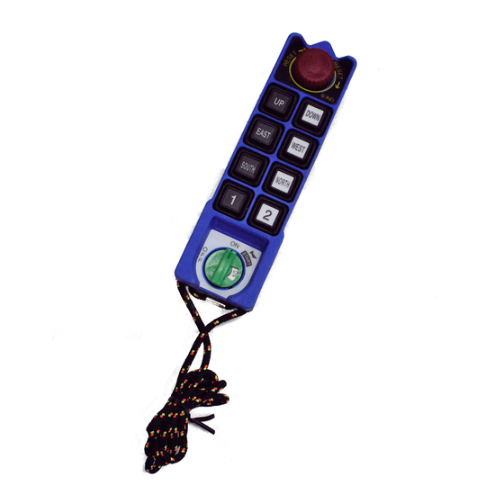
Page 6: Transmitter Configuration
Operation TRANSMITTER CONFIGURATION... -
Page 7: Receiver Configuration
RECEIVER CONFIGURATION... -
Page 8: General Operation
GENERAL OPERATION Turn on the main power switch of the equipment (Crane). Install 2 AA batteries in the battery box in the Transmitter. Make sure the “+” and “-“ directions are correct. Attach Transmitter battery door with screws. ... - Page 9 Receiver Voltage Selection There are two types of power voltages (DC and AC) available for the Series 310. 1) DC Type: Input Voltage: 12~24 VDC Relay Contact: 10A-36 VDC 2) AC Type: Three different AC transformers: 48/110/220V, 48/220/380V, 110/220/380V. Please disconnect the Receiver’s power, select the proper voltage, and plug in the connector.
- Page 10 ID-Code Remote Setting ID-Code remote setting allows the user to pair the new Transmitter or Receiver if one of them is damaged. Using ID-Code remote setting will make both the Transmitter and Receiver have the same ID-Code. 1) Please make sure of the following conditions before ID-Code remote setting: ...
-
Page 11: Changing The Frequency
Changing the Frequency It is easy to change the frequency of the Series 310 simply by replacing corresponding frequency crystals in both the Transmitter and the Receiver. Note: To replace a new crystal, please note that there are two kinds of frequencies (VHF and UHF) available. - Page 12 Batteries Two AA size alkaline batteries are required for the Transmitter. The LED will flash green when the battery power is sufficient. The LED will flash red when the battery power is low. The operating distance will become shorter and intermittent when the battery is low.
- Page 13 Wiring Diagram INMOTION-310...
Need help?
Do you have a question about the 310 Series and is the answer not in the manual?
Questions and answers