
Related Manuals for MINICAM SoloPro

Summary of Contents for MINICAM SoloPro
- Page 1 Pipeline Inspectio on System Users Gui Unit t 4 Yew Tre ee Way, Ston necross Par Golb borne, rrington, A3 3JD. Unit ted Kingdo Rev G - 07/20 Page: 1...
- Page 2 Notice The information contained in this document is subject to change without notice. Mini-Cam Ltd. makes no warranty of any kind with regard to this material, including but not limited to, the implied warranties of merchantability and fitness for a particular purpose.
-
Page 3: Certification
Certification Mini-Cam Ltd. certifies that this product met its published specifications at the time of shipment from the factory. Regulatory Information CE Declaration We Mini-Cam Ltd. Unit 4 Yew Tree Way, Stonecross Park, Golborne, Warrington, WA3 3JD hereby declare that the product SOLO Pro Pipeline Inspection System, part no CCU-205 to which this declaration refers is in compliance with the following standards or standardizing documents: EN61000-6-2:2005... -
Page 4: Fcc Declaration
FCC Declaration Note: This equipment has been tested and found to comply with the limits for a Class A digital device, pursuant to part 15 of the FCC Rules. These limits are designed to provide reasonable protection against harmful interference when the equipment is operated in a commercial environment. - Page 5 CONDITIONS OF THE LIMITED WARRANTY Disassembling the camera, coiler, control unit or any part of the system, without approval of the manufacturer, is forbidden! Non-compliance of this direction will result in the loss of the warranty. The beginning of the warranty period is the date of delivery. This limited warranty does not cover damage due to improper treatment of the system, inadequate maintenance, alteration, repair, normal wear and tear or external causes like lightning, fire or frost.
-
Page 6: Manual Conventions
WARNING Warning denotes a hazard. It calls attention to a procedure which, if not correctly performed or adhered to, could result in injury or loss of life. Do not proceed beyond a warning note until the indicated conditions are fully understood and met. CAUTION Caution denotes a hazard. -
Page 7: Table Of Contents
Table of Contents Certification......................3 CE Declaration ....................3 FCC Declaration ....................4 LIMITED WARRANTY ..................4 Manual Conventions ....................6 Preparing for Use ..................9 1.1. What you'll find in this chapter ............. 9 ... - Page 8 5.3. Show/Play function ................24 5.4. Copy function ..................24 5.5. Rename ....................24 5.6. Delete function .................. 25 5.7. Un-mounting external memory ............25 5.8. USB / SDHC Media Types ..............26 ...
-
Page 9: Preparing For Use
1. Preparing for Use 1.1. What you'll find in this chapter This chapter describes the process of getting the SOLO Pro Pipeline Inspection System ready to use when you have just received it. 1.2. Initial Inspection Inspect the shipping container for damage. If the shipping container or cushioning material is damaged, keep it until you have verified that the contents are complete and you have tested your SOLO Pro mechanically and electrically. -
Page 10: Physical Installation
When the batteries are fully charged, the battery charger automatically switches off, preventing battery damage due to overcharging. Therefore the external power supply may be left connected and switched ‘on’ indefinitely with no ill effects. WARNING: Never plug the control unit into a power supply source that is more than 12 volts DC nominal. -
Page 11: Environmental Operating Temperature Consideration
1.8. Environmental Operating Temperature Consideration The operating temperature of the SOLO Pro is between -10 to +40 degrees Celsius, not in direct sunlight. Care should be taken during the operating of this equipment, especially in hot environments, to shade it from direct sunlight. Radiant heat from the sun can cause the equipment to heat up to temperatures exceeding +60 degrees Celsius. -
Page 12: Display Features
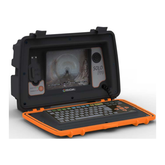
2. Display Features 2.1. What you'll find in this chapter This chapter describes the characteristics of the front panel LCD display. 2.2. Introduction The front panel of the SOLO Pro unit houses an 8” Liquid Crystal Display (LCD) which is used to display ‘live’ and recorded video and ‘on screen’ menus. The display parameters such as contrast, brightness, colour and backlight intensity may be adjusted to suit the environment in which the unit is being viewed. -
Page 13: Status Icons
re is an are ea below th he picture w where the f ilename of a recorded d or played back vide eo file is dis played. Thi is is not rec corded with h the pictur If po ower saving g mode is e enabled, th e screen ba... -
Page 14: Display Brightness
Inte ernal batte ry – This Ico on shows w whether an ternal powe er source is available ( power plug n) or if the unit is ope erating on i nternal bat tteries attery icon). . The ‘gaug ge’ to the ri ght of this icon ows the ava... -
Page 15: Keyboard
3. Keyboard 3.1. What you'll find in this chapter This chapter describes how functions are selected from the keyboard 3.2. Keyboard description. The keyboard may be divided into seven sections as shown in Fig 4.1 (below). Recorder Control Keys System Control Keys Text Control Keys Video Command Keys Text Entry Keys... -
Page 16: System Control Keys
his key allow ws the user r to contro l the colour r of the tex xt and the ackground on which t the text app pears. his key turn ns the free t text on and d off. Thus the user ca an turn free e text... -
Page 17: Recorder Control Keys
Thes se two key s control th he core vide eo function ns of the sys stem. his key gen erates a sn apshot pict ture of the video curre ently being splayed. Th his may be used whilst t viewing liv ve video, re ecording or aying back... -
Page 18: Text Entry Keys
he help key y displays th he key symb bols, identi fies the ow wner name, erial numbe er. The curr rent softwa re version i is also displ layed in the e title 3.9. . Text Entry y Keys Thes se keys hav ve the same... -
Page 19: Video File Format
An example filename is shown below:- 100106_1059-Minicam.avi This indicates that the file was recorded on the 6th January 2010 and started at 10:59. Mini-Cam is the default filename and .avi shows that the file is in the motion video AVI format 4.5. -
Page 20: Sonde
Camera and LCD Dimming – The camera illumination and LCD backlight will dim after a period of inactivity. The options are: Never / 5 / 15 / 30 minutes. Automatic Shutdown – When the SOLO Pro is powered only by internal batteries this feature will power down the SOLO Pro after a period of inactivity. -
Page 21: Service Centre
IMPORTANT: DO NOT remove the external media during the update. NOTE: SOLO Pro will not allow the user to use the “Software Update” feature if the internal batteries are less than 40% charged. This feature will then appear greyed out in the menu. 4.12. -
Page 22: Gallery
5. G Gallery 5.1. . What you 'll find in t this chapte This s chapter de escribes ho w the key is u sed to acce ess and ma nipulate reco orded surve ey video file 5.2. . Gallery M Pres ssing the key d... - Page 23 Selected memory type The ‘tick’ next to one of the memory types shows which one is selected for viewing and where the video files are automatically recorded to. Thus it is possible to set the system up so that all files are recorded to internal memory, to an external USB memory stick, or an SD/SDHC card.
-
Page 24: Show/Play Function
5.3. . Show/Play y function Show/Play y menu ent try will be h highlighted in yellow. Press gain and th sele cted video will play or r will be dis splayed. An a alternative way to play y a video fi le is to pres ss the ‘play y’... -
Page 25: Delete Function
5.6. Delete function The Delete function permanently removes the selected file from the system. If this function is selected from the Gallery menu, then a window is displayed asking the user to confirm that this file is to be deleted and if the user presses OK then the file is removed. -
Page 26: Usb / Sdhc Media Types
en it OK to remove th he selected memory, th he red cros ss will disap ppear so on ly the gree en arrow w will remain, indicating t that the me emory may y be remove ed.. For the e SD mory and U USB memor... -
Page 27: Playing Back A Recording
ile this is p progress ico on displaye ed, no act ion, such a as removin g a USB mory stick or an SD c card, shou ld be attem mpted as it t may resu lt in corrup pted or b bad files. -
Page 28: Zoom
6.6. . Zoom survey pict ture may be e zoomed i in to see sm mall details in the surv To z zoom in pre ess the Zoo om key (see section 3.4 4). Pressing g this key o nce will zoo om in by a a factor of 1... -
Page 29: Text Entry, Symbols And Graphics
7. T Text Entr y, Symbo ols and G raphics 7.1. . What you 'll find in t this chapte This s chapter de escribes the e way in wh hich free te ext and ons screen grap phics may b ente ered on to t the screen... -
Page 30: Free Text Entry
7.4. . Free Text Entry Free e text may b be typed on n the scree n using the e text entry keys. Free text can be turn ned on and off and ma anipulated whilst a su urvey is bein ng recorded d, all chang bein... -
Page 31: Symbols & Graphics
7.8. . Symbols & & Graphics mbols & Gra aphics can b be added to o the recor ding, such as an arrow w or circle, high hlight an ar rea of intere est. Pres ss the ey to bring up the Sym mbol and Gr raphics me... - Page 32 Attention: Your product is marked with this symbol. It means that used electrical and electronic products should not be mixed with general household waste. There is a separate collection system for these products. Information on Disposal for Business Users: Attention: If you want to dispose of this equipment, please do not use the ordinary dust bin! Used electrical and electronic equipment must be treated separately and in accordance with legislation that requires proper treatment, recovery and recycling of...
Need help?
Do you have a question about the SoloPro and is the answer not in the manual?
Questions and answers