Table of Contents
Advertisement
Quick Links
AX-309
MIXER AMPLIFIER DIGITAL
ON
OFF
- Output:
- Load impedance:
- Distortion:
- Passing band:
- Tone controls:
- Power supply:
- Maximum consumption:
- Dimensions:
- Weight:
- Colour:
- Presentation:
300 W. RMS five-input power amplifier
with built-in mixer,
for professional audio applications.
-Microprocessor-controlled-
ON
MOD
AUX-5
MIC/AUX-4
TECHNICAL CHARACTERISTICS
300 W. RMS at 1 KHz.
16 (L 70 V.).
W
33 (L 100 V.).
W
from 50 Hz. to 17 Khz.
at 100 Hz.
14 dB.
at 10 KHz.
13 dB.
230 VAC (50/60 Hz.).
600 VA.
430x376x140 mm. (3 U).
19.8 Kgs.
Black.
epoxy / metal.
Insertion connector for external signal processors.
8 bits control microprocessor.
Main
Avda. BARCELONA, 24
08970 - SANT JOAN DESPÍ
Office
BARCELONA - ESPAÑA
Tel: 34-93 477 28 54
Fax: 34-93 261 17 52
ude@udeaudio.com
UDE reserves the right to modify the technical characteristics of its products without previous notice
MIC/AUX-3
MIC/AUX-2
MIC/AUX-1
4 configurable inputs, balanced microphone / auxiliary.
microphone: sensitivity = 0,7 mV.
4
.
impedance = 200 to 600
8
.
voice equalisation filter = -15 dB at 100 Hz.
phantom alimentation = 12 VDC
auxiliary: sensitivity = 190 mV.
1%.
impedance = 47 K .
1 auxiliary input (remote controlled modulation cut).
Direct signal input to mixer bus.
output = 400 mV / 600
input = 400 mV / 4700
Madrid
Delegation
MASTER
4
3
Digital
2
F
1
.
sensitivity= 190 mV
impedance= 47 K .
sensitivity = 500 mV
impedance = 600 .
Signal output.
level = 800 mV
impedance = 600 .
Insertion.
.
.
C/ LUIS I, 88, 3ª planta
28031 - MADRID
ESPAÑA
Tel: 34-91 311 60 76
Fax: 34-91 450 19 97
centro@udeaudio.com
5
6
7
8
610.104A
1
16
Advertisement
Table of Contents

Related Manuals for Ude AX-309


Summary of Contents for Ude AX-309
- Page 1 BARCELONA - ESPAÑA ESPAÑA Tel: 34-93 477 28 54 Tel: 34-91 311 60 76 Fax: 34-93 261 17 52 Fax: 34-91 450 19 97 ude@udeaudio.com centro@udeaudio.com 610.104A UDE reserves the right to modify the technical characteristics of its products without previous notice...
-
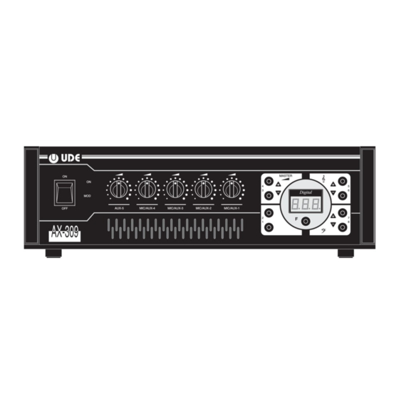
Page 2: Front Controls
AX-309 Front controls MASTER Digital AUX-5 MIC/AUX-4 MIC/AUX-3 MIC/AUX-2 MIC/AUX-1 On/off switch Input nr. 1 control Power On indicator Master (digital control) Modulation indicator Display Input nr. 5 control Bass (digital control) Input nr. 4 control Treble (digital control) Input nr. 3 control Microprocessor functions selector Input nr. - Page 3 AX-309 Description The AX-309 amplifier includes inside a microprocessor that digitally controls and supervises the main functions of the apparatus. This particularity, along with the universal signal input system, which can be configured by the engineer installing the system, make for a reliable, versatile and easy-to use device.
-
Page 4: General Characteristics
AX-309 General characteristics Amplifier section: - Electronic protection against short-circuits in output. - Power supply suspend. - Excess temperature (110 C in the power radiator) detector. In the event of overheating caused by a ventilation obstruction, a safety device will be triggered. When temperature conditions revert to normal this devise switches off automatically. -
Page 5: Installation
AX-309 How to start up the unit INSTALLATION: Install the optional accessories (if applicable). See graphic. Configure inputs 1, 2, 3 and 4 (music microphone, voice microphone, music microphone with phantom power supply, voice microphone with phantom power supply or auxiliary input). See graphic. - Page 6 AX-309 Configuration of convertible inputs REMOVE THE COVER AND SET THE JUMPERS AS FOLLOWS JUMPER SETTINGS AUX 4 AUX 3 AUX 2 AUX 1 AUXILIARY MUSIC MICROPHONE Configuration Configuration Configuration Configuration INPUT 4 INPUT 3 INPUT 2 INPUT 1 VOICE...
-
Page 7: Connection Diagram
AX-309 Connection diagram AUX-5 MIC/AUX-2 MIC/AUX-3 MIC/AUX-4 MIC/AUX-1 230 VAC BASIC CONNECTION SYSTEM OPTIONAL ELEMENTS WX-19 Antilarsen module CA-01 AUXILIARY AMPLIFIER WX-30 Chime and priority module WX-33 Simple priority module CA-01 CA-32 PX-9 EG-31 PRE-AMPLIFIER EQUALIZER MICROPHONE SOUND SOURCE - Radio, CD, Cassette, etc. - Page 8 AX-309 How to assemble the WX-19 module WX-19 - Remove the top cover of the unit. - Remove the bracket for the WX-19 module. - Assemble the WX-19 module in the aforementioned bracket using the screws supplied. - Fit the 6-lead connection as shown.
- Page 9 AX-309 How to assemble the WX-30 / WX-34 module WX-30 - Remove the top cover of the unit. - Remove the bracket for the WX-30 / WX-34 module. - Assemble the WX-30 / WX-34 module in the aforementioned bracket using the screws supplied.
-
Page 10: Block Diagram
AX-309 Block diagram DIGITAL CONTROL 230 VAC +12 VDC 230 VAC MICROPROCESSOR +5 VDC VOL 1 ± 15 VDC MIC/AUX-1 ± 92 VDC VOL 2 MIC/AUX-2 VOL 3 MIC/AUX-3 CONTROL MATCHING DIGITAL SIGNAL VOL 4 300 W RMS MIC/AUX-4 MASTER VOL 5 Th 65 C. -
Page 11: Installer Menu
AX-309 INSTALLER MENU The installer can use the keyboard and associated display to perform the following operations: Access the installer menu (Fig. 1) Change the password in the installer menu (Fig. 2) Select the load impedance of the unit manually (4 , 8 , 70V/16 , 100V/33 ). - Page 12 AX-309 INSTALLER MENU VOLUME (MASTER) MANUAL Fig. 5 Fig. 3 TREBLE IMPEDANCE BASS SELECTION ADJUSTMENT MANUAL ADJUSTMENT CURRENT IMPEDANCE VALUE Z= 4 MIN. MIN. MIN. Z= 8 MAX. MAX. MAX. L= 70V MEMORIZE VALUES L= 100V RECOVER VALUES FROM MEMORY...
- Page 13 AX-309 INSTALLER MENU EDIT (CORRECT) AN Fig. 8 EXISTING PROGRAMME (E.g. edit programma 7) COPY THE CONTENT OF ONE Fig. 7 PROGRAMME TO ANOTHER (E.g. copy programme 2 to 3) PRESET PROGRAMME MENU CALL UP PROGRAMME TO SELECT PRESET PROGRAMME...
-
Page 14: Warning Messages
AX-309 Warning messages SIGNAL POWER SUPPLY SATURATION SIGNAL SATURATION: Occasionally, when the amplifier is operating normally, the display may show a flashing message This means that the signal that reaches the mixer is excessive in one or several of the 6 inputs. - Page 15 AX-309 USER MENU Use in mode 1 (standard) Operation Start-up in mode 1 (standard) with remote-controlled message priority START-UP REMOTE-CONTROLLED MESSAGE PRIORITY RECOVER MEMORIZED SETTINGS INDICATE VOLUME VALUE INDICATE VOLUME VALUE MESSAGE PRIORITY MENU ISSUE PRIORITY MESSAGE MIN. MIN. MIN.
- Page 16 AX-309 USER MENU Use in mode 2 (programmed) Operation Start-up in mode 2 (programmed) with remote-controlled message priority START-UP REMOTE-CONTROLLED MESSAGE PRIORITY START-UP IS ALWAYS WITH PROGRAMME 1 CURRENT PROGRAMME MESSAGE PRIORITY MENU PROGRAMME ISSUE PRIORITY MESSAGE PROGRAMME PROGRAMME PROGRAMME...
Need help?
Do you have a question about the AX-309 and is the answer not in the manual?
Questions and answers