Table of Contents
Advertisement
Quick Links
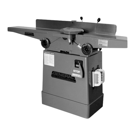
SETUP & OPERATION MANUAL
FEATURES
Large surface, ground cast-iron tables for
stability and added support when feeding
longer stock.
Heavy-duty, three-knife cutter head for
clean, fast, superior finish cuts.
Jackscrew system for quick, easy knife
adjustment.
Large, heavy-duty, center-mounted cast-
iron fence with 90° and 45° positive stops.
Independent in-feed and out-feed table
adjustment handwheels.
4" dust collection outlet included.
Built-in rabbeting ledge.
2 hand-paddle style push blocks with
onboard storage mounts included.
Extra long 66 1/4" tables
SPECIFICATIONS
TABLE SIZE
7 1/4" x 66 1/4" (184 x 1683 mm)
MAXIMUM CUTTING WIDTH
6" (152 mm)
MAXIMUM CUTTING DEPTH
1/2" (13 mm)
RABBETING CAPACITY
1/2" (13 mm)
FENCE SIZE
4" x 38" (102 x 965 mm)
CUTTER HEAD SPEED
5000 RPM
NUMBER OF KNIVES
3/HELICAL
BASE DIMENSIONS (L X W)
24" x 13 3/4" (610 x 349 mm)
MOTOR
1 HP , 110/220 V, 13/7 A
SHIPPING WEIGHT / NET WEIGHT
423 LBS (192 kg) / 340 LBS (154 KG)
6" DELUXE JOINTER
MODEL
#80-125L/LHC
VERSION 1 - REVISON 1 (August 16
© COPYRIGHT GENERAL INTERNATIONAL 2011
th
, 2011)
Advertisement
Table of Contents

Related Manuals for General 80-125L

Summary of Contents for General 80-125L
- Page 1 24" x 13 3/4" (610 x 349 mm) MOTOR 1 HP , 110/220 V, 13/7 A SHIPPING WEIGHT / NET WEIGHT 423 LBS (192 kg) / 340 LBS (154 KG) VERSION 1 - REVISON 1 (August 16 , 2011) © COPYRIGHT GENERAL INTERNATIONAL 2011...
- Page 2 GENERAL® INTERNATIONAL 8360 Champ-d’Eau, Montreal (Quebec) Canada H1P 1Y3 Telephone (514) 326-1161 • Fax (514) 326-5555 • www.general.ca THANK YOU for choosing this General ® International model 80-125L/LHC 6” Deluxe Jointer. This jointer has been carefully tested and inspected before shipment and if properly used and maintained, will provide you with years of reliable service.
- Page 3 2 years (24 months) from the date of purchase. General® and General® International agree to repair or replace any part or component which upon examination, proves to be defective in either workmanship or material to the original purchaser during this 2-year warranty period, subject to the “conditions...
-
Page 4: Table Of Contents
......22 - model 80-125L only Install the pulley guards ....11 Helical cutter head insert reversal / Install the dust port . -
Page 5: Rules For Safe Operation
To help ensure safe operation, please take a moment to learn the machine’s applications and limitations, as well as poten- tial hazards. General® International disclaims any real or implied warranty and holds itself harmless for any injury that may result from improper use of its equipment. -
Page 6: Additional Safety Instructions For Jointers
Additional Safety Instructions for Jointers Because each shop situation is unique, no list of safety guidelines can ever be complete. The most important safety feature of any shop is the knowledge and good judgement of the user. Use common sense and always keep safety considerations, as they apply to your individual shop conditions, first and foremost in mind. -
Page 7: Electrical Requirements
We suggest you ask your local General International distributor to recommend qualified electricians in your area (or perhaps one of their own technicians) who GROUNDING INSTRUCTIONS can make this conversion properly and safely. -
Page 8: Basic Functions
This 6” jointer is offered with 2 different cutterhead options as follows: • Model 80-125L M1 – 6” jointer with standard 3-knife cutter head and a closed base stand and handwheel con- trolled infeed and outfeed table height adjustments. -
Page 9: Unpacking
Carefully unpack and remove the jointer, its components and tools from its shipping container and check for mis- sing or damaged items as per the list of contents below. NOTE: Please report any damaged or missing items to your GENERAL® INTERNATIONAL distributor immediately. LIST OF CONTENTS A - JOINTER BED ................1... -
Page 10: Clean Up
CLEAN UP The protective coating on the jointer tables prevents rust from forming during shipping and storage. Remove it by rubbing with a rag dipped in kerosene, mineral spirits or paint thinner. (Dispose of potentially flammable solvent- soaked rags according to manufacturer’s safety recommendations.) A putty knife, held flat to avoid scratching the surface, may also be used to scrape off the coating followed by clean-up with solvent. -
Page 11: Pulley Parallel Alignment
PULLEY PARALLEL ALIGNMENT Hold a straight edge to the pulleys to check p u l l e y alignment A. If the pulleys are aligned: Fully tighten the flange bolts that secure the jointer bed to the stand with the supplied 14 mm wrench. If the pulleys are not aligned: Adust the position of the jointer bed on the stand C to obtain pulley alignment then fully tighten the flange... -
Page 12: Install The Fence & Fence Locking Handle
INSTALL THE FENCE & FENCE LOCKING HANDLE Install the fence on the jointer by sliding the T-slot A Install the fence locking handle C as shown in D. under the fence on the guide bar B. INSTALL THE FENCE TILT LEVER Thread the knob on the fence tilt lever Screw the fence tilt lever into the threaded hole in the fence B. -
Page 13: Install Base Door
Attach the base door to the base using 4 x mm Phillips screws and flat washers. ASSEMBLE THE KNIFE SETTING GAUGE Note: Models 80-125L only. This gauge is not required on models 80-125LHC due to the helical cutter head. Using a pair of pliers, push a c-clip into the inner grooves on each end of the knife setting gauge rod. -
Page 14: Connecting To A Dust Collector
If you do not already own a dust collection system consider contacting your General® International dis- tributor for information on our complete line of dust collection systems and accessories or visit our Web Site at www.general.ca. -
Page 15: Adjusting And Setting The In-Feed
ADJUSTING AND SETTING THE IN-FEED TABLE HEIGHT / DEPTH OF CUT The depth of cut is set by raising or lowering the in-feed WORKPIECE table. Refer to the recommended depth of cut settings in sec- tion “Basic Jointing Operations Instructions”, on page 20. THE MAXIMUM DEPTH OF CUT FOR ONE PASS IS 1/8”. -
Page 16: Adjusting The Fence & Checking
ADJUSTING THE FENCE & CHECKING / SETTING THE FENCE STOPS The fence stops allow you to position the fence at specif- ic pre-set angles in relation to the tables without having to measure each time you return to that angle. Due to wear and vibration, fence stops can over time become misaligned and should be checked periodical- ly and re-set if necessary. -
Page 17: Checking Knives
CHECKING KNIVES The knives have been factory set to the exact same height in the cutter head. However we suggest that you verify that the knives are properly set prior to first use. Accurate work results can only be achieved when all three knives are properly installed and set to the exact same height in the cutter head. -
Page 18: Selecting Boards Suitable For Jointing
2. Only boards with the grain running more or less length- wise are suitable for jointing C. ALWAYS JOINT IN THE GENERAL DIRECTION OF THE GRAIN. JOINTING AGAINST THE GRAIN OR JOINTING END GRAIN IS DANGEROUS AND MAY CAUSE THE WORKPIECE TO SHATTER. -
Page 19: Checklist Before Starting
CHECKLIST BEFORE STARTING VERIFY ALL CHECK POINTS BEFORE STARTING. FAILURE TO COMPLY CAN RESULT IN SERIOUS INJURIES. • Make sure you and any assistants are wearing safe appropriate workshop attire. Roll up long sleeves, secure long hair and remove any jewelry: watches, rings, bracelets or anything that could become caught in the mov- ing parts, potentially causing serious injury. -
Page 20: Basic Jointing Operations
BASIC JOINTING OPERATIONS SURFACE PLANING 1. Inspect the stock before starting & remove any foreign objects or debris. 2. Set the depth of cut as required (1/32" is recommend- ed for face planing - Less for hard wood or wider stock.) 3. -
Page 21: Maintenance
To maintain even insert wear always reverse or replace all 16 inserts each time knife replacement is required. When needed, replacement inserts B can be ordered through your local General International distributor under part #30-443. -
Page 22: Model 80-125L Only
KNIFE SETTING OR REPLACEMENT - MODEL 80-125L ONLY Properly setting all three knives is essential to achieving accurate work results. Properly set knives will last longer and also keep their edge (sharpness) longer by equally sharing the cutting workload. You may use the supplied knife setting gauge to help you set the knives to the correct height whenever re-setting or changing knives. -
Page 23: Helical Cutter Head Insert Reversal / Replacement - Model 80-125Lhc Only
HELICAL CUTTER HEAD INSERT REVERSAL / REPLACEMENT - MODEL 80-125LHC ONLY INSERT EDGES ARE VERY SHARP. USE CARE WHEN HANDLING INSERTS. Using the one of the two supplied Allen keys, loo- Thoroughly clean the housing D before reinstal- sen but do not remove the nut and screw A and re- ling a knife-holder/chip breaker and insert. -
Page 24: Adjusting The Gibs
3. Repeat these steps for the out-feed table gib nuts E, then verify and adjust (if necessary) the out-feed table height following the instructions in section “Adjusting and Setting the Out-Feed Table Height” on page 19. MODEL 80-125L/LHC MODELS 80-125L/LHC... -
Page 25: Recommended Optional Accessories
We offer a large variety of products to help you increase convenience, productivity, accuracy and safety when using your jointer Here’s a small sampling of optional accessories available from your local General International dealer. For more information about our products, please visit our website at www.general.ca... -
Page 26: Parts List & Diagrams
MODEL 80-125L 65-2 65-1 65-2 65-1... - Page 27 PARTS LIST 80-125L REF N0. PART N0. DESCRIPTION SPECIFICATION 80100-01 PHILLIPS HEAD SCREW 5/32" - 32NC x 5/8" 80100-02 RETAINER 80100-03 SPRING KNOB 80125-01 SPRING 80100-05 RETAINING WASHER 80100-06 RIVET 2 x 5 80125-02 CHIP DEFLECTOR 80125-03 SPRING PIN 3 x 20...
- Page 28 PARTS LIST 80-125L REF N0. PART N0. DESCRIPTION SPECIFICATION 80100-58 5 x 5 x 25 80100-59 BEARING 6203-2NSE 80100-60 BEARING HOUSING 80100-61 CUTTERHEAD PULLEY 80125-23 FENCE BODY 80125-24 COUNTERSUNK SCREW 5/16" - 18NC x 1-1/2" 80100-65 FENCE HANDLE ASSEMBLY 65-1...
- Page 29 PARTS LIST 80-125L REF N0. PART N0. DESCRIPTION SPÉCIFICATION 80100-115 FLAT WASHER 4.3 x 10 x 1.0T 80100-116 PHILLIPS HEAD SCREW 1/8" - 40NC x 3/8" 80100-117 MOTOR WIRE SJT16AWG x 3C x 700 MM 80125-57 SWITCH ASSEMBLY 118-1 80125-58...
- Page 30 HELICAL CUTTER HEAD - 100H MODEL 80-125LHC ONLY PARTS LIST 80-125LHC REF N0. PART N0. DESCRIPTION SPECIFICATION QTY 100H-01 CUTTER HEAD 100H-02 SCREW 100H-03 100H-04 KNIFE-HOLDER / CHIP-BREAKER 30-443 CARBIDE INSERT (STANDARD) 30X12X1.5MM (T) 100H-06 CARBIDE INSERT (RABBETING) 30X12X1.5MM (T) 100H-07 T HANDLE ALLEN KEY 100H-08...
-
Page 31: Notes
Notes... -
Page 32: Contact Information
MODELS 80-125L/LHC 8360 Champ-d’Eau, Montreal (Quebec) Canada H1P 1Y3 Tel.: (514) 326-1161 Fax: (514) 326-5565 - Fax: (514) 326-5555 - Parts & Service / Order Desk orderdesk@general.ca www.general.ca IMPORTANT When ordering replacement parts, always give the model number, serial number of the machine and...
Need help?
Do you have a question about the 80-125L and is the answer not in the manual?
Questions and answers