Advertisement
Advertisement

Related Manuals for SainSmart Genmitsu 3018-PROVer

Summary of Contents for SainSmart Genmitsu 3018-PROVer
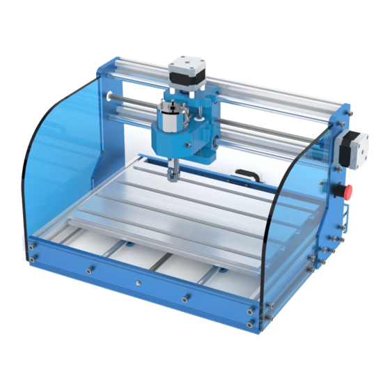
- Page 1 Genmitsu CNC Router 3018-PROVer V1.2 Jun 2020...
-
Page 2: Table Of Contents
Contents ............................Welcome ............................Disclaimer ........................... Part 1 - Unboxing ....................Part 2 - Mechanical installation ..........................Part 3 - Wiring ......................... Part 4 - Software Setup ....................Part 5 - Using Offline Controller ......................Part 6 - Troubleshooting... -
Page 3: Welcome
Welcome Thank you for purchasing the Genmitsu 3018-PROVer CNC Router from SainSmart. Included in your package will be a Micro SD card. On the Micro SD Card, you will find: ● Assembly instruction videos ● PDF version of this manual ●... -
Page 4: Disclaimer
SainSmart cannot control the conditions in which you assemble your Genmitsu CNC machine or verify if it was done properly. We do not assume responsibility and expressly disclaim liability for loss, injuries, damage, or expense arising out of, or in any way connected with the assembly, handling, storage, use, or disposal of the product. -
Page 5: Part 1 - Unboxing
Part 1 - Unboxing Please make sure all the following parts are included. If you are missing any part or have any questions, please email us at support@sainsmart.com. X-Axis/Z-Axis Gantry Y-Axis Base Assembly Spindle with ER11 tail ER11 1/8" Collet... - Page 6 Stepper Motor Cable, X-Axis, 17cm Limit Switch Cable X LIM+, 15cm Offline Controller Cable Stepper Motor Cable, Y-Axis, 52cm Limit Switch Cable X LIM-, 53cm Stepper Motor Cable, Z-Axis, 28cm Limit Switch Cable Y LIM+, 30cm Limit Switch Cable Y LIM-, 60cm Limit Switch Cable Z LIM+, 34cm Limit Switch Cable Z LIM-, 40cm Emergency Stop...
- Page 7 Sealing Strip, Y-Axis, 27cm (30) Cable Tie (10) Cable Holder Spacer Template Tool Sealing Strip, X-Axis, 34cm Genmitsu CNC Router 3018-PROVer V1.2 May 2020 (4) Rubber MicroSD Card User Manual Cable Protector MicroSD Card Foot Reader (2) ABS (8) M5 10mm Bolt (2) M3 20mm Screw (4) M3 20mm T-Slot Nut (12) M5 14mm Bolt...
- Page 8 Optional Accessories (Not Included) Consider following optional upgrades or accessories to make your CNC experience better! You can find them on www.sainsmart.com. Save 10% with discount code PROVER10 Resin Board for CNC Acrylic Sheet for CNC, 5.5W Laser Module CNC Router Bits Essential Kit...
-
Page 9: Part 2 - Mechanical Installation
Part 2 - Mechanical installation 2.1 Preparing your base assembly What you will need Allen Wrench Set, (2) M6 16mm Bolt Y-Axis Base Assembly Step 1: Flip the Y-Axis Base Assembly upside down and remove the cable ties from the bearing mount. Step 2: Align the Aluminum Build Plate center slot with the blue Y-Axis lead screw mount as shown in the picture. - Page 10 2.2 Installing limit switches & cable holders to Y-Axis What you will need (10) M3 5mm Screw (6) Cable Holder (2) Limit Switch Screwdriver Y-Axis Base Assembly Step 1: Locate the Limit switch mount indents on the inner side of the frame. One on each side as shown below. Step 2: Install cable wire holders in the pre-drilled holes next to the limit switches, using the 3mm screws.
- Page 11 Step 3: Install one limit switch on each side by tightening the 3mm screws.
- Page 12 2.3 Installing Rubber feet to Y-Axis Base Assembly What you will need Allen Wrench Set, (4) Rubber Foot Y-Axis Base Assembly Step 1: Locate the 4 pre-drilled holes and install the rubber feet on each corner using the Allen wrench...
- Page 13 2.4 Installing Limit Switches to X-Axis/Z-Axis Gantry What you will need (2) Limit Switch (3) Cable Holder (2) ABS Spacer Screwdriver X-Axis/Z-Axis Gantry (6) M3 5mm Screw (2) M3 20mm Screw...
- Page 14 Step 1: The first limit switch to install is on the stepper motor side. You will need the two white ABS spacers and the longer 20mm M3 screws for this step. Locate the two pre-drilled holes on the inside of the gantry next to the lead screw, as shown in the picture below.
- Page 15 2.5 Install T-Slot Tension Nuts What you will need Y-Axis Base Assembly Spacer Template Tool Step 1: Position the Y-Axis base assembly so that the step motor is facing your right hand side. Step 2: Insert (6) Tension T-Slot Nuts on each side. Position near the back of the machine (Stepper Motor Side).
- Page 16 2.6 Install Y-Axis Base to X / Z Axis Gantry What you will need (12) M5 Allen Wrench Set, X-Axis/Z-Axis Gantry Y-Axis Base Assembly Spacer Template Tool 14mm Bolt Step 1: Set the X-Axis / Z Axis Gantry over your Y-Axis Base Assembly as shown below. Step 2: Place the Acrylic Spacer template underneath the gantry to prop a side up at a time.
- Page 17 Step 3: Install (6) M5 14mm screws into the T-Slot nuts. Keep the screws loose until you finish the other side. Step 4: Repeat the process on the opposite side. Now you can tighten all 12 M5 screws. M5 14mm Bolt x 12...
- Page 18 2.7 Install the Spindle What you will need Allen Wrench Set, Spindle with ER11 tail ER11 1/8" Collet Step 1: Unscrew the black collet collar from the spindle and insert the collet. Make sure the collet is locked in place by pushing it. Then screw the the collet collar back to the spindle.
- Page 19 Step 2: Loosen the Spindle Mount Hex Screw Step 3: Slide the spindle into the mount until the external sleeve of the spindle is fully inserted. Step 4: Tighten the Hex screw to secure the Spindle. Do not over tighten the screw, as it can damage the mount.
- Page 20 2.8 Install the Acrylic Baffles What you will need Allen Wrench Set, (8) M5 10mm Bolt (8) M5 20mm T-Slot Nut (2) Acrylic Baffle You want to identify the left baffle and the right baffle first, by placing the baffle along side the frame to fit the shape.
- Page 21 Step 3: Now tighten the M5 bolts to secure the baffle. Repeat the steps to install the other side.
- Page 22 Congratulations! Now your machine frame is fully assembled! Now let's move onto wiring!
-
Page 23: Part 3 - Wiring
Part 3 - Wiring PCB Board Diagram X Axis Y Axis Z Axis Spindle motor motor motor 0-5V spindle controller speed Power control signal supply 24V 5A PWM signal output USB connection Laser module ESTOP Z-Probe X Y Z axis limit/home switch Offline controller... - Page 24 PCB Label Description Mark Description Mark Description USB interface Laser module interface -LAS+ 24V power interface PWM signal output interface 24VDC -PWM+ Power ON GND 0-5V 0-5V spindle controller speed control signal Power OFF Spindle Spindle motor interface X Axis motor interface Offline controller (Note: Only Offline controller connect to our offline controller)
- Page 25 3.1 Install the Main Control Board What you will need (4) M3 8mm Screw (4) M3 20mm T-Slot Nut Main Control Board Step 1: Locate the four pre-drilled holes in the corners Step 2: Position the frame so that the back of the machine is facing you.
- Page 26 Step 3: Slide the board horizontally to leave about 30mm of space between the board and the left edge of the machine as shown below. Step 4: Now you can tighten all (4) 8mm bolts so the T-Slot nuts lock the board into the frame. 30mm...
- Page 27 3.2 Connecting X-Axis Limit Switches What you will need Limit Switch Cable X LIM+, 15cm Limit Switch Cable X LIM-, 53cm Sealing Strip, X-Axis, 34cm (Limit switch cables have black plugs on both ends) Position the machine so that the main control board is facing you. Step 1: Connect one end of the Limit Switch Cable X-LIM (+) (+ is near the stepper motor) to the X+ limit switch near the stepper motor, and connect the other end to the socket marked X-LIM (+) to the main control board (There are six white sockets toward the bottom of the board).
- Page 28 Step 2: Connect Limit Switch Cable X-LIM (-) to the X- limit switch on the right side. Run the cable behind the control board, along the top channel of the bottom beam, then loop around the control board. Plug the other end of the cable to the control board X-LIM(-) socket.
- Page 29 Step 3: Press the sealing strip (flat side out) over the cable into the top channel of the bottom beam.
- Page 30 3.3 Connecting Y-Axis Limit Switches What you will need Limit Switch Cable Y LIM+, 30cm Sealing Strip, Y-Axis, 27cm Limit Switch Cable Y LIM-, 60cm Step 1: Connect one end of the Limit Switch Cable Y-LIM (+) to the Y+ limit switch (the one on the step motor side) Step 2: Connect one end of the Limit Switch Cable Y-LIM (-) to the Y- limit switch...
- Page 31 Step 3: Connect both cables to the corresponding sockets on the control board Step 4: Press the sealing strip (flat side out) over the Y- limit switch cable into the side beam.
- Page 32 3.4 Connecting Z-Axis Limit Switches What you will need Limit Switch Cable Z LIM-, 34cm Limit Switch Cable Z LIM-, 40cm Step 1: Insert the short Limit Switch Cable Z-LIM (+) into Z+ limit switch (on top, near the stepper motor). Connect the other end to main control board.
- Page 33 3.5 Connecting the Stepper Motor cables What you will need Step 1: Locate all three stepper motors. X-Axis Stepper Motor Cable, X-Axis, 17cm stepper motor is on the side of the machine. Y-Axis Stepper Motor Cable, Y-Axis, 52cm stepper motor is on the bottom of the machine in the Stepper Motor Cable, Z-Axis, 28cm back.
- Page 34 Step 2: Connect each stepper motor with the labeled cable to the main control board. Note that the end of 4-pin plug goes to the main board.
- Page 35 3.6 Connecting the Spindle cables What you will need Spindle Cable, 35cm Step 1: Connect spindle cable to the top of the spindle, RED to M+ and BLACK to M-. Step 2: Connect the other end of the spindle cable to the main control board.
- Page 36 3.7 Install the Emergency Stop button What you will need Emergency Stop Button with Cable Step 1: Remove black plastic nut and the square lock washer on th back side of the button. Step 2: Insert Emergency button into the pre-cut hole underneath the X-Axis Stepper Motor.
- Page 37 Step 4: Connect the cable to the main control board. See position show below. Usage: Pushing the button will trigger emergency stop. The button will stay engaged once pushed. The button can only released when twisted clockwise. This prevents double pushing the button from releasing the trigger.
- Page 38 Final Checks Lubricate the Threaded rods on all the axes, It is suggested to use a ‘Dry’ PTFE based lubricant or similar (Not included) to help stop any Lubricate dust sticking to the rods. the axes Note: Part of the normal maintenance is to periodically clean the threaded rods and re-lubricate as needed.
- Page 39 A Brief Glossary Glossary The aluminum base with slots to allow stock to be clamped to it. Moved by the Y axis. Whatever material you secure to the bed and cut or engrave. Stock Geometric Code, the language of the commands that the router understands, ca be used for specific G-Code commands or combined into a file (normally .nc) of instructions to make something.
-
Page 40: Part 4 - Software Setup
Part 4 - Software Setup Please visit SainSmart Online Resource Center installing drivers and software for your CNC. https://docs.sainsmart.com/3018-prover The driver and software can also be found on the included Micro SD card. Part 5 - Using Offline Controller https://docs.sainsmart.com/3018-prover-offline... -
Page 41: Part 6 - Troubleshooting
Part 6 - Troubleshooting Hopefully everything works as expected, but if not: Symptom Check The USB cable is inserted correctly. The USB Driver has been installed correctly. Candle shows a Serial port error The correct COM Port and a baud rate of 115200 are set in Candle. message in the Console window The Offline Controller is not connected. - Page 42 Copyright © 2020 by SainSmart All rights reserved. This manual or any portion thereof may not be reproduced or used in any manner whatsoever without the written permission of the publisher, except for the use of brief quotations embodied in critical reviews and certain other noncommercial uses permitted by copyright law.
- Page 43 Genmitsu Desktop CNC & Laser www.sainsmart.com support@sainsmart.com Vastmind LLC, 5892 Losee Rd Ste. 132, N. Las Vegas, NV 89081...
Need help?
Do you have a question about the Genmitsu 3018-PROVer and is the answer not in the manual?
Questions and answers