Table of Contents
Advertisement
Quick Links
Advertisement
Table of Contents

Related Manuals for Neptune Systems PM1


Summary of Contents for Neptune Systems PM1
- Page 1 Apex Probe Module 1 (PM1) Setup Guide...
-
Page 2: Table Of Contents
Initial Connections ......................3 Startup ..........................4 VERIFY THE INSTALLATION ................... 4 UPDATE PROBE MODULE FIRMWARE ................5 CONFIGURE THE PM1 ..................... 5 PH PROBE SETUP ......................5 Ph Probe Calibration ......................6 pH Probe Maintenance ......................8 ORP PROBE SETUP ......................8 ORP Probe Calibration ...................... -
Page 3: Introduction
Compatible with all Apex systems. • PHYSICAL INSTALLATION The PM1 should be securely mounted in a location free from moisture. Use wood screws through the mounting tabs of the probe module case or if mounting on drywall, use drywall anchors (mounting hardware not included). -
Page 4: Startup
Apex Display: Setup – Module Setup – Modify Name – from this screen, you can see all AquaBus modules installed on the system. Web Interface: Configuration – Module Setup – Verify the probe module is listed in the Apex Module List. Apex Probe Module 1 (PM1) - Setup Guide Page 4... -
Page 5: Update Probe Module Firmware
Apex system, the system will automatically add the PM1 to the Apex configuration. If you wish to use the PM1 port for a pH probe, follow the steps listed in the section titled pH Probe Setup below. If you intend to use an ORP probe, skip to the section titled ORP Probe Setup later in this manual. -
Page 6: Ph Probe Calibration
Web Interface: This option is not available from the Web Interface. NOTE: If temperature compensation is to be used on the PM1, a temperature probe must be connected and enabled on the PM1. The system temperature probe cannot be use for temperature compensation of a probe connected to a PM1. - Page 7 Acquire the proper pH calibration solution packets and place in aquarium water (unopened) to acclimate them to the system temperature. If automatic temperature compensation is to be used, place the temperature probe connected to the PM1 in the same aquarium water with the calibration packets.
-
Page 8: Ph Probe Maintenance
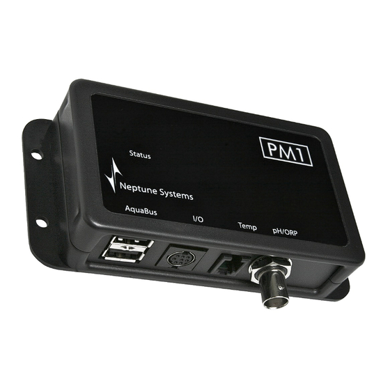
The number in the probe name corresponds to the AquaBus address assigned to the probe module. If not already done, The ORP probe is connected to the port labeled pH/ORP on the PM1. Push the BNC female connector on to the male connector and turn ¼ turn clockwise to lock the connector place. -
Page 9: Orp Probe Calibration
6. Remove the pH probe from the 7.0/Quinhydrone Calibration Solution, rinse it in tap water, gently shake the excess water off the probe, and place the probe in the 4.0/Quinhydrone Calibration Solution. Periodically swirl the probe in the solution to Apex Probe Module 1 (PM1) - Setup Guide Page 9... -
Page 10: Orp Probe Maintenance
SWITCH INPUTS The PM1 has a Mini DIN8 connector for switch inputs labeled I/O. These inputs can be used for switches, float switches, water sensors, flow sensors, etc. Switch inputs connected to probe modules will be identified as Swx3_2, Swx5_3, etc. The first number in the switch name corresponds to the AquaBus address assigned to the probe module. -
Page 11: Programming
ORP probes connected to probe modules will be identified as “ORPx3”, “ORPx4” and so on. The number in the probe name corresponds to the AquaBus address assigned to the probe module. Apex Probe Module 1 (PM1) - Setup Guide Page 11... - Page 12 The second number corresponds to the switch input number (1 - 6). NOTE: The pH and ORP readings from the PM1 can be added to the Apex Display and Web Interface Status Screens. See the section titled Display Setup in the Apex Setup and Programming Guide for more information.
-
Page 13: Neptune Systems Limited Warranty
1 year from the date of purchase. If repair or adjustment is necessary and has not been the result of abuse, Neptune Systems warrants this product to be free from defects in material and workmanship for a period of 1 year from the date of purchase. - Page 14 Apex Probe Module 1 (PM1) - Setup Guide Page 14...
Need help?
Do you have a question about the PM1 and is the answer not in the manual?
Questions and answers