Table of Contents
Advertisement
Advertisement
Table of Contents
Troubleshooting

Subscribe to Our Youtube Channel
Related Manuals for Neptune Systems AquaController Apex Classic


Summary of Contents for Neptune Systems AquaController Apex Classic
- Page 1 Apex Classic Setup and Programming Guide...
-
Page 2: Table Of Contents
WELCOME TO AQUACONTROLLER APEX ........... 1 FEATURES ....................1 TABLE OF ACRONYMS ................3 TYPICAL AQUACONTROLLER SYSTEM COMPONENTS ........ 3 SETUP OVERVIEW ..................5 PHYSICAL INSTALLATION ................ 6 Base System Initial Connections ..............6 NETWORK SETUP ..................8 Automatic Network Configuration (default) ............ 8 Manual Network Configuration (Optional) ............ - Page 3 Temperature Probe Setup ................. 30 Temperature Probe Calibration ..............31 Temperature Probe Maintenance ..............32 pH Probe Setup ..................32 Ph Probe Calibration ................33 pH Probe Maintenance................35 ORP Probe Setup ..................35 ORP Probe Calibration ................36 ORP Probe Maintenance ................39 Conductivity Probe Setup (optional) ............
- Page 4 Moon Lighting ..................62 Programming Feed Timers ................ 62 Variable Speed Port Programming .............. 63 Pump Profile Type .................. 64 Ramp Profile Type ................. 65 Editing Profiles ..................65 Programming with Profiles ..............66 DISPLAY SETUP ..................67 Edit Status Screens ................. 67 Locking the Display ..................
- Page 5 Resonant Waves ..................106 Alternate with Variable Speed Pumps ............107 Growing Surge with Variable Speed Pumps ..........109 APPENDIX 5 – TROUBLESHOOTING AND HELP ........110 APPENDIX 6 – TELNET COMMANDS ............110 INDEX ....................111 NEPTUNE SYSTEMS LIMITED WARRANTY ..........115...
-
Page 6: Welcome To Aquacontroller Apex
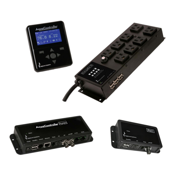
WELCOME TO AQUACONTROLLER APEX Congratulations on your purchase of the AquaController Apex system. The AquaController Apex System delivers an expandable, professional quality aquarium controller at hobbyist prices. The AquaController Apex is the most flexible, expandable system on the market today. FEATURES •... - Page 7 • Alternate power port can provide backup power in case the EnergyBar(s) lose power so email alarms can be sent, status and logs can be viewed on the Apex Display. • Clock, program and calibration settings are backed up in the case of a power outage.
-
Page 8: Table Of Acronyms
• Completely silent operation on the 6 solid state switched outlets (5 amps max per outlet). • Solid State outlets feature a soft-start mechanism for reduced pump wear. • 2 Relay controlled outlets for higher power switching (each 10 amps max). •... - Page 9 • Mounting screws • Installation and Getting Started Guide Apex Classic Setup and Programming Guide v2.2 Page...
-
Page 10: Setup Overview
SETUP OVERVIEW The AquaController Apex can be setup using either the Apex Display Module or the Apex Web Interface or a combination of both methods. This manual provides you with instructions to perform setup functions from both the display and Web Interface. -
Page 11: Physical Installation
Whichever interface you use for setup, you can be up and running with a basic AquaController Apex configuration in as little as 15 minutes. However, to take full advantage of the advanced programming features may take additional time and you may find yourself adding functions and enabling features every few days until you get it customized just the way you like it. - Page 12 Plug one end of the included AquaBus cable into one of the AquaBus ports on the Apex Base Module and the other end into one of the EnergyBar 8 AquaBus ports. Plug the Apex Display Module AquaBus cable into an available AquaBus port on the EnergyBar 8 or Apex Base Module (the display can be connected to any available AquaBus port on the entire AquaBus system).
-
Page 13: Network Setup
12V adapter to power the Apex Base Module. This AC adapter is available through your authorized dealer or from Neptune Systems and should be connected to a quality surge suppressor to protect your system. - Page 14 address from the network to which it is connected (if DHCP is enabled on the network which is common for home networks). Soon after system startup, the Apex base module will request IP configuration from the DCHP server and configure itself with that information. Once configured, the Apex Web Interface can be accessed by typing the following URL into a compatible web browser from a computer browser on the same network: http://apex...
-
Page 15: Manual Network Configuration (Optional)
WARNING: Be aware that when using DHCP, the IP addressed assigned to the Apex base module can and will change from time to time. This can cause problems for browsers in finding the Apex Web Interface on your network. In addition, if the Apex is to be accessed outside its home network, manually configuring a fixed IP address is recommended to avoid firewall problems. - Page 16 In addition to the IP address, you need the Subnet Mask, and the IP address of the Default Gateway and DNS Server. These can also be determined by referring to the documentation that came with your home network router. Alternately, you can determine this information from another PC on the same network to which the Apex Base Module will be connected.
- Page 17 Web Interface: Configuration – Network Setup – click in the Gateway box and type the default gateway, press the Update Network Settings button to save changes. Apex Classic Setup and Programming Guide v2.2 Page...
-
Page 18: Configure The Apex Hostname (Optional)
To set the Primary DNS: Apex Display: System – Net Setup – DNS Server – use the up/down arrows to change the number of the highlighted character, use the left/right arrows to select the character to change, when done, press OK. Web Interface: Configuration –... -
Page 19: Configure The Apex Web Interface Port Number (Optional)
is restarted. This is not a limitation of the Apex, rather the DNS service running on your home network. CONFIGURE THE APEX WEB INTERFACE PORT NUMBER (OPTIONAL) The Apex Base Module Web Interface uses an industry standard port number of 80. -
Page 20: Restart The Apex (Optional)
NOTE: Web Interface Credentials are only editable from the Apex Display Module. WARNING: The Web Interface Credentials can be viewed and changed from the Apex Display Module. If the Apex Display Module is in a non- secure area, the Apex Display should be secured with a Display Password, see the section titled Locking the Display for more information. - Page 21 Mailbox Username and Password – The credentials used to log in and send mail (typically the same credentials are used to check mail). These credentials are only required if your mail provider requires you to log in to access the SMTP server (usually not required for ISP mailboxes while on the ISP’s network).
- Page 22 Apex Classic Setup and Programming Guide v2.2 Page...
-
Page 23: Enable/Disable Email Authentication
To: Address Apex Display: System – Email Setup – To address – use the up/down arrows to change the highlighted digit, use the left/right arrows to select the highlighted digit, when done, press OK. Web Interface: Configuration – Network setup – click in the To Address field and type the appropriate email address, press the Update Network Settings button to save changes. -
Page 24: Send A Test Alarm Email
User Name (only required if Email Authentication is enabled) Apex Display: System – Email Setup – User name – use the up/down arrows to change the highlighted digit, use the left/right arrows to select the highlighted digit, when done, press OK. Web Interface: Configuration –... -
Page 25: Configuring The Apex To Be Accessible From The Internet
mail If you don’t understand the debug messages please email the log to support@neptunesys.com, and we’ll help you determine what is wrong. This function can be used to send a test email to verify end-to-end operation of all components needed to send email alarms. Apex Display: System –... -
Page 26: Clock Setup
will use when trying to access the controller from outside your home network (a cell phone browser or other computers on the internet). If your internet connection has a dynamic IP address assignment (most do), your WAN IP address may change from time to time. When the WAN IP address changes, you will need to determine and use the new IP address which can be a hassle. - Page 27 Enable/disable Automatic Clock Set feature Apex Display: System – Clock Setup – Auto Set: – push the Select button to toggle this feature on and off. Web Interface: Configuration – Clock setup – click the Enable or Disable radio button next to Auto Clock Set. Manually set the Tank Time Apex Display: System –...
-
Page 28: Apex Module Setup
many seconds to adjust the internal clock per day. For example if the clock is gaining 1.5 seconds per day, a value of -1.5 would be entered to offset this inaccuracy. The AquaController Apex uses this value to slow its time down by 1.5 seconds each day. - Page 29 digital inputs for connecting float switches, sensors, etc. PM1 temperature and pH or ORP probes are enabled/disabled and calibrated using the same menus and procedures as the Apex Base Module probes, see the section titled Probe Setup for more information. Apex Classic Setup and Programming Guide v2.2 Page...
-
Page 30: Probe Module 2
PROBE MODULE 2 AquaController Apex Probe Module 2 (PM2) adds a Temperature and Conductivity ports to the Apex system. This module connects anywhere on the AquaBus and includes 2 AquaBus ports for flexible connection options. PM2 also includes 6 digital inputs for connecting float switches, sensors, etc. PM2 temperature and Conductivity probes are enabled/disabled and calibrated using the same menus and procedures as the Apex Base Module probes, see the section titled Probe Setup for more information. -
Page 31: Configure An Apex Module
dropdown list, click the Rename radio button, click the Submit Module Update button. CONFIGURE AN APEX MODULE Some AquaBus modules have configuration settings that can be updated through the Config Modules menu found from the Apex Display at Setup – Module Setup – Config Module. -
Page 32: Connecting Legacy Modules
unique address is assigned, set the switches on the Direct Connect module using the instructions found in user manual for the legacy module. CONNECTING LEGACY MODULES All legacy modules (except PX-1000) are connected to the port labeled Control on the Apex Base Module. If more than one legacy module is used, it is daisy- chained one to the next just as they were with previous AquaController systems. -
Page 33: Adding Legacy Outlets
prone to errors as X10 communications can be. If X10 must be used, the X10 Control Interface (i.e. IM513) is plugged in to the Control port on the AquaController Apex Base Module or in to the last legacy device in the Control chain. - Page 34 Apex Display: Setup – Outlet Setup – Delete Outlet – use the up/down arrows to highlight the outlet to delete, push Select, push OK to confirm. Web Interface: Configuration – Module Setup – in the Delete Outlet: box near the middle of the page, select the outlet to delete from the dropdown box, click the Delete Outlet button.
-
Page 35: Probe Expansion Px-1000
PROBE EXPANSION PX-1000 The PX-1000 adds Temperature, pH and pH/ORP ports to the AquaController system. It connects to the port labeled I/O on the Apex Base Module. Connect Temperature, pH and ORP probes to the PX-1000 as needed. Power for the PX- 1000 is supplied by the included AC adapter. -
Page 36: Temperature Probe Calibration
these temperature probes is the same for all probes on the system. The Base Module temperature probe will be identified as “Temp”, the probe on the PX1000 Probe Expansion as “TempA”, “TempB” and so on, and probes on Apex Probe Modules (PM1, PM2, etc) as “TmpX3”, “TmpX4”... -
Page 37: Temperature Probe Maintenance
arrow keys to choose the probe you wish to calibrate, press Select, then use the up/down arrow keys to select the correct probe temperature, press Select when done. Web Interface: This option is not available from the Web Interface. TEMPERATURE PROBE MAINTENANCE Temperature probes do not need maintenance other than cleaning on an infrequent basis. -
Page 38: Ph Probe Calibration
NOTE: Do not let the tip of the pH probe dry out as damage to the probe will result. If you are not using your pH probe for an extended period of time, make sure the tip is submerged in Probe Storage solution at all times. If storage solution is not available, tap water can be used (RODI water should not be used). - Page 39 The Apex system uses a 2 point calibration system which results in very accurate readings between the 2 points and less accurate readings outside the points. Choose the calibration solutions based on the range of pH the probe is expected to read.
-
Page 40: Ph Probe Maintenance
8. Use the up/down arrow keys to select the High Calibration Solution used, push Select. 9. Dry the High Calibration Solution packet off and carefully open the corner of the low solution, just enough to get the pH probe inserted in the packet. Remove the pH probe from the Low Calibration Solution, rinse it in probe storage solution (or tap water), gently shake the excess solution off the probe, and place the probe in the High Calibration Solution. -
Page 41: Orp Probe Calibration
ports and calibration of the connected probes is the same for all probes on the system. The Base Module ORP probe will be identified as “ORP”, the ORP probe on the PX1000 Probe Expansion as “ORPA”, “ORPB” and so on, and probes on Apex Probe Module 1 (PM1) as “ORPx3”, “ORPx4”... - Page 42 AquaController Apex includes the ability to perform a 2 point calibration if desired. Special calibration solution must be made from standard pH 4.0 and 7.0 calibration solution by dissolving Quinhydrone powder in the solutions. Simply dissolve Quinhydrone powder into the 4.0 and 7.0 solutions until the powder no longer dissolves.
- Page 43 If the calibration measurements were not accurate or were out of range, the calibration may fail which will be indicated on the Apex Display. In this case, the default calibration settings will be used. You can attempt the calibration procedure again, however this usually indicates that the ORP probe is too far out of range and should be replaced.
-
Page 44: Orp Probe Maintenance
ORP PROBE MAINTENANCE ORP probes should be periodically cleaned for best performance. The period between cleanings is up to the user but typically every 1-3 months is normal. To clean the probe, gently brush the sides and tip of the probe with a soft brush to remove any debris. -
Page 45: Conductivity Range
CONDUCTIVITY RANGE The PM2 supports 4 conductivity ranges to support the conductivity measurement of various solutions. The four ranges are described in Table 2 - Conductivity Range Options: Range Units Calibration Description Solution 0 to 850 447 S/cm Typically used to S/cm measure the purity of RO/DI water. -
Page 46: Temperature Compensation
arrow keys to select the range for that port, press OK when done or Exit to discard changes. Web Interface: This option is not available from the Web Interface. TEMPERATURE COMPENSATION Conductivity measurements are temperature dependent. The degree to which temperature affects conductivity varies from solution to solution. -
Page 47: Conductivity Probe Maintenance
3. Use the Up and Down buttons to select the calibration solution. Press the select button when the correct value is displayed. See Table 2 - Conductivity Range Options for the recommend calibration solution. 4. Place the Conductivity probe into the calibration solution. Wait for the numbers on the bottom of the LCD screen to stop changing. - Page 48 • The DO probe should not be located above air diffusers or in area with air bubbles in the water column. Air bubbles will cause erroneous readings. • The DO probe should mounted with the membranes pointing up so that bubbles do not collect on the membrane surface.
-
Page 49: Dissolved Oxygen Range
DISSOLVED OXYGEN RANGE The PM3 supports 2 dissolved ranges as described in the table below: Range Units Description 0 to 200% Percent of dissolved oxygen in the water column. 100% indicates a saturated DO level. 0.0 to The parts/million of oxygen in the 20.0 ppm water column. -
Page 50: Dissolved Oxygen Probe Maintainence
membrane. Allow 10 minutes for the probe to reach temperature equilibrium. Do not place probe in direct sunlight. 4. Wait for the numbers on the bottom of the LCD screen to stop changing. When the display stops changing press the select button. 5. -
Page 51: Programming Outlets
PROGRAMMING OUTLETS DEFAULT PROGRAM To make getting started with the AquaController Apex easy, outlets on installed outlet modules are setup with default assignments and programs that can be used as-is, modified to suit your specific needs or erased and reprogrammed to whatever you need. -
Page 52: Pump
Off time – the time the light should turn off in 24 hour format (hours:minutes). Shutdown probe – the name of the temperature probe that should be monitored to shutdown the outlet in an overheating situation (Temp, TempA, Tmpx3, etc). Device shutdown value –... -
Page 53: Ph Control
Fallback – the state the outlet should switch to if contact between the EnergyBar and base module is lost (on or off). Probe name – the name of the temperature probe that should be used to control this outlet (Temp, TempA, Tmpx3, etc). On temperature –... -
Page 54: Editing Outlet Programming
On when – when set to High, the outlet is On when the ORP value is above the High Value setting. When set to Low, the outlet is On when the ORP value is below the Low Value. (Low or High). EDITING OUTLET PROGRAMMING The program for an outlet can be edited from either the AquaController Apex Display or the Web Interface. - Page 55 from switches, the state of other outlets and more. To enable the Advanced Programming mode, simply set the Program or Control Type to Advanced in the Outlet Setup as described in the section titled Editing Outlet Programming. Once an outlet is configured for Advanced Programming, you edit, add and delete commands from the Apex Web Interface.
-
Page 56: Virtual Outlets
Web Interface: Configuration – Outlet Setup – in the Outlet box near the top of the page, select the outlet to edit from the dropdown box. When the Control Type for this outlet is set to Advanced, an Advanced Setup box will appear on the lower half of this page with the existing Advanced program displayed. -
Page 57: Order Of Operation
This will make Sump_Low turn on and off in response to the float switch which can be included on a Status Screen or referred to in other outlet programming. In addition, creating Virtual Outlets for switch inputs that have meaningful names makes programming and reading your program much easier as you do not have to remember that “Switch1”... -
Page 58: Repeat Interval
In this example, the state of the pH command is overruled by the state of Light1 and they all are overruled by Switch1 commands. Whenever Switch1 is closed, the outlet is on and whenever it is open, the outlet is off, the first 2 commands are essentially ignored. -
Page 59: Programming With Hysteresis
NOTE: The repeat interval is only used for legacy control bus devices like the DC8, DC4HD, etc. AquaBus devices always have the correct outlet state once communication is restored. To modify the Repeat Interval (default is 5 minutes): Apex Display: Setup – Outlet Setup – Repeat Interval –use the up/down arrow keys to select the repeat interval, press OK to save or Exit to discard changes. -
Page 60: Defer
The Minimum Time command will keep an outlet in the on or off state for a minimum amount of time. For example, in the Light Wizard, when the light is turned off because the tank temperature rose above the Off Temp, the Minimum Time command is used to keep the lights off for a minimum of 30 minutes to prevent the light outlet from being switched on and off rapidly when the temperature is hovering around the set point. -
Page 61: Triggering Alarms Or Events On Power Outages
By default, the following alarm trigger points have been programmed into the Email Alarm outlet: Set Off If Temp > 82.0 Then ON If Temp < 75.0 Then ON Theses statements will trigger an email to be sent when the temperature measured by probe Temp is greater than 82 or less than 75. -
Page 62: Sample Alarm Email
Web Interface: This option is not available from the Web Interface. Power Monitor allows you to connect your EnergyBar 8 to an uninterruptible power source and by connecting an Neptune Systems Apex 12V power supply to a non-backed up power source, be able to trigger events when the power fails. -
Page 63: Switch Inputs
CO2_3_7 is OFF Auto Ozone_3_8 is ON Manual Power Failed: Mar 01 2010 18:50:42 Power Restored: Mar 01 2010 18:51:11 Power OK: EB8_3 (28 Minutes - 01.6 Amps) SWITCH INPUTS The AquaController Apex has a Mini DIN8 connector for switch inputs labeled I/O. These inputs can be used for switches, float switches, water sensors, flow sensors, etc. -
Page 64: Identifying Ports And Switches On Expansion Modules
Input 5 Input 6 Reserved Ground Table 4 – Switch Input Connector Pin-out The pin-out of the connector is shown in Figure 6 - Switch Input Connector. Connect switches to the AquaController Apex by connecting one wire from the mechanical switch to the ground pin (pin 8), and the other wire from the switch to one of the six digital inputs (pin 1-6). -
Page 65: Seasonal Programming
pHx3, ORPx3, Tmpx3 and Switchx3_1, Switchx3_2 are probes and switches on the Probe Expansion assigned AquaBus number 3. pHx4, ORPx4, Tmpx4 and Switchx4_1 and SwitchX4_2 are probes and switches on the Probe Expansion assigned AquaBus number 4. Probes and switches on legacy probe expansion PX-1000 are identified with ascending letters. -
Page 66: Seasonal Lighting Adjustment
If Temp > RT+0.2 then OFF This will turn the heater outlet on when the Temp probe measures the Regional Temperature less .3 degrees. The heater outlet will turn off at Regional Temperature plus .2 degrees. The following command could be used to trigger an alarm: If Temp >... -
Page 67: Moon Lighting
Light2: If Sun 060/-045 Then ON The first statement turns Light1 on at sunrise of the particular day based on the settings in the Seasonal Table and off at sunset. Light2 turns on 60 minutes after sunrise and turns off 45 minutes before sunset. MOON LIGHTING The AquaController Apex can be used to simulate the moonrise and moonset as well as varying the intensity of the light source. -
Page 68: Variable Speed Port Programming
NOTE: The Pump Wizard included a parameter to turn off the pump when a Feed Timer is activated. See the section titled Programming with Wizards for information on how to program the Feed Timer using the Pump Wizard. To configure the duration of the Feed Timer: Apex Display: Setup –... -
Page 69: Pump Profile Type
PUMP PROFILE TYPE The Pump Profile is typically used to oscillate the speed of a pump from one speed to a higher speed and back. Popular use of this feature is to create resonant or chaotic waves in larger tanks depending on if the waves are synchronized or not. -
Page 70: Ramp Profile Type
WARNING: Tunze recommends an intensity of 30% or higher for Tunze Streams Pumps. For best results and longevity of your pumps, never set the Minimum Intensity lower than 30%. For example, assume the following settings: Synchronize = off Divide by 10 = off Initial off time = 10 On time = 15 Off time = 20... -
Page 71: Programming With Profiles
Setup – Profile Setup – Edit Settings – use the up/down arrows to highlight the Profile you wish to edit, press Select. Highlight the parameter you wish to change and push Select, use the up/down arrow keys to change the value, press Select when done. Push Save to save or Exit to discard changes. -
Page 72: Display Setup
DISPLAY SETUP The Apex Display features an attractive, backlit graphic display and buttons to program and operate the AquaController Apex system and to monitor the status of the aquarium. The Apex Display can be configured with 4 different Status Screens, each of which can be configured to display tank time, tank parameters measured be probes (pH1, pH2, ORP, Temp, etc.) as well as the status of outlets and alarms that are most important to you. -
Page 73: Locking The Display
LOCKING THE DISPLAY The AquaController Apex Display can be protected by the Display Lock. When enabled, users will have to unlock the display to access programming options. The Apex Display will still show the status of the system and the feed timers can be used when Display Lock is enabled. -
Page 74: Display Contrast
Web Interface: This option is not available from the Web Interface. To set the Night Brightness: Apex Display: System – Display Setup – Night Brightness – use the up/down arrows to choose a comfortable brightness to use during the day, when done, press OK. - Page 75 Dashboard is comprised of a palette and tiles. Your palette is like a blank canvas. Tiles contain the status of outlets, probes and embedded URL’s. You can have up to 4 Dashboards on a controller. You access and configure them via your web pages on the Dashboard menu.
-
Page 76: Embedding Streaming Video
EMBEDDING STREAMING VIDEO The Dashboard has a special tile that is blank in the Unused Tiles. This tile can be configured with a URL of any web cam that can stream video in a MJPEG format with a URL. USB web cams typically can’t stream video out to the internet. -
Page 77: About Tiles
When you think you have the proper syntax for your camera, you can test it in your browser. Just enter the full URL into an empty browser window. You might get prompted for a user name and password for your camera. If you get a video stream you’re good to go. - Page 78 Apex Display: System – Sound Setup – Key Press Beep – Press Select to toggle between ON and OFF. Web Interface: This option is not available from the Web Interface. Apex Classic Setup and Programming Guide v2.2 Page...
-
Page 79: Using The Aquacontroller Apex
USING THE AQUACONTROLLER APEX VIEWING STATUS Status Screens can be viewed from both the Apex Display and the Web Interface. The information shown on the Status Screens are edited according to the instructions in the section titled Edit Status Screens. The 4 dots in the upper right corner of the Apex Display screen indicate which of the 4 Status Screens is currently displayed. -
Page 80: Graphing
temporarily override the outlet but automatically return it to normal operation after a period of time. See the section titled Programming Feed Timers for more information on setting up Feed Timers. Outlets can set to the following 3 states: AUTO – The outlet will turn on and off based on the AquaController program ON or MANUAL ON –... - Page 81 display graphs of all probes enabled on the system as well as the electrical current draw through each EnergyBar 8 connected to the system. Apex Classic Setup and Programming Guide v2.2 Page...
- Page 82 To view Graphs: Apex Display: Data Log – Graph – will display the first graph for the current day. Press the up/down arrows to change the graph displayed (Temp, pH, ORP, AMP, etc.). Push the left/right arrows to change the day that is graphed.
-
Page 83: Feed Timer Operation
Figure 10 - Web Interface Graph NOTE: Since the graphs are generated from the Data Logs, graphs in the past may display more or fewer probes based on the Apex system configuration on the day of the graph. FEED TIMER OPERATION The AquaController Apex has 4 user defined feed timers. -
Page 84: Logging
To Cancel the Feed Timers Apex Display: Control/Status – Feed Cancel or from the Feed Timer display, push the Cancel button. The Feed Timer will be canceled and all outlets returned to their normal function as if the Feed Timer was never invoked. -
Page 85: Power Fail Log
Web Interface: Data Log – select the day and length of log you wish to view from the selection boxes near the top of the page and click the Update Button to view the log. Figure 11 - Data Log POWER FAIL LOG All power failures to individual EnergyBars and Apex Base Modules are logged by the AquaController Apex. -
Page 86: Self Test
WARNING: Initializing memory will result in resetting the AquaController Apex programming information back to the factory default sate. YOUR PROGRAMMING WILL BE ERASED. Make sure you save your configuration information by following the instructions in the section titled Load/Save Configuration and you are sure you know what you are doing before using these utilities. -
Page 87: Load/Save Configuration
displayed. If your base module fails the Self test, please contact Neptune Support through one of the methods listed in Appendix 5 – Troubleshooting and Help. The Self Test screen is also an easy way to check the firmware version and date installed as well as the Base Module serial number. -
Page 88: Xml Menu
NOTE: The Save function creates a file titled Apexcfg.bin in the location you specify. You can rename the file but leave the file extension as .bin for easy identification. All configuration information (Outlet, Profile, Display, Network and Miscellaneous) is stored in this single file. To Load the AquaController Apex configuration: Apex Display: This option not available from the Apex Display. -
Page 89: Preparing The Update
NOTE: Other computer platforms including Apple Macintosh OS 10 can be used to run the Apex Flash Utility. See the Readme.txt file included with the firmware download for more information. PREPARING THE UPDATE 1. Install Microsoft .Net framework version 3.5. a. - Page 90 2. Double-click Apex Flash Utility.exe the Apex Flash Utility should open as shown in Figure 13 - The Apex Flash Utility. Figure 13 - The Apex Flash Utility 3. The File name field contains the name of the firmware file you are about to flash to the Apex Base Module.
-
Page 91: Updating The Apex Base Module Web Interface
b. If you have changed the Administrator User Name and Password, enter the current credentials (current user name can be viewed from the Apex Display at System – Net Setup – Admin Login, current password can be viewed from the Apex Display at System – Net Setup –... -
Page 92: Upgrading Apex Modules
a. The update process should take less than 3 minutes depending on network speeds. UPGRADING APEX MODULES The firmware version of software installed on the Apex Base Module can be flashed to each Apex Module through the AquaBus using the directions in this section . - Page 93 3. Start the firmware update by pressing the firmware update button. 4. Wait for the firmware update to timeout. 5. Re-apply power to the Apex base module. The status LED will flash yellow, and connect to the flash utility. Error – Object reference not set to an instance of an object. Typical Cause –...
-
Page 94: Appendix 1 - Apex Display Menu Structure
APPENDIX 1 – APEX DISPLAY MENU STRUCTURE Apex Classic Setup and Programming Guide v2.2 Page... -
Page 95: Appendix 2 - Display Icons
APPENDIX 2 – DISPLAY ICONS The table below contains the graphical icons that will be displayed on the AquaController Apex Display when configured on an outlet. See the section titled Editing Outlet Programming for instructions on how to change the icon for an outlet. -
Page 96: Appendix 3 - Programming Reference
APPENDIX 3 – PROGRAMMING REFERENCE DEFER The Defer command requires that the internal program state of the outlet be in the specified state for a specified period of time before actually switching the state of the outlet. The internal program state is determined by executing all the commands in the outlet program listed before and after the defer command. -
Page 97: If Dow
IF DOW The If DoW command is used to control outlets based on the Day of the Week. If DoW S-T-TFS Then ON In this example, the outlet will be on all days of the week except Monday and Wednesday. Syntax If DoW XXXXXXX Then Y XXXXXXX = place a the capital initial for the days when the statement should be... -
Page 98: If Moon
IF MOON The If Moon command allows for an outlet to be controlled based on the moonrise and moonset of the lunar cycle. The numeric fields are used to adjust when the outlet is switched either before or after the lunar cycle time. The first number is the number of minutes to add or subtract from the moonrise time, and the second number is the number of minutes to add or subtract from the moonset time. -
Page 99: If Outlet
IF OUTLET The If Outlet command is used to control an outlet based on the state of another outlet. If Outlet Light1 = ON Then OFF In this example, whenever outlet Light1 is on, the outlet containing this command will be off. Syntax If Outlet O = X Then Y O = the name of the Outlet to be followed... -
Page 100: If Power
IF POWER The If Power command allows for outlets to be controlled in response to whether or not power is present to the Apex base unit or any of the EnergyBars. If Power Apex OFF 010 Then ON In this example, if power to the Apex base module is off, and for 10 minutes after power is restored the outlet will be turned on. -
Page 101: If Sun
IF SUN The If Sun command allows for an outlet to be controlled based on the sunrise and sunset variations listed in the Seasonal Table. The numeric fields are used to adjust when the outlet is switched either before or after the time in the Seasonal Table. -
Page 102: If Temp
IF TEMP The If Temp command allows for an outlet to be controlled in response to the temperature measurement. If Temp > 80 Then ON In this example, whenever probe Temp measures more than 80 degrees, the outlet is on. Syntax If TempX C T Then Y TempX = the name of the temperature probe (Temp, TempA, TempB, Tmpx3,... -
Page 103: Minimum Time
MINIMUM TIME The Minimum Time command will keep an outlet in the on or off state for a minimum amount of time. To use this command, specify the amount of time you would like it to be in effect and whether you want it to keep the outlet off or on. Both a Minimum on and a minimum off time can be specified on a given outlet. -
Page 104: Set
The Set command is used to set an outlet on or off. Set = ON In this example, if the outlet will be set on. Syntax Set Y Y = ON to turn the outlet on or OFF to turn the outlet off NOTE: Commands later in the outlet program may override this command. -
Page 105: Automatic Top Off
If Temp > 78.0 Then OFF Chiller <Real Outlet 6> Fallback Off If Temp > 79.0 Then ON If Temp < 78.0 Then OFF CO2 <Real Outlet 7> Fallback Off If pH > 8.00 Then ON If pH < 7.90 Then OFF Ozone <Real Outlet 8>... - Page 106 switches (when the float is not raised by the water, the switch is open, i.e. does not make a complete circuit). Connect one end of each switch to the ground connection on the I/O connector on the AquaController Apex. Connect the other float switch lead from Sump_Low to input 1, and the other lead of Sump_High to input 2.
-
Page 107: Kalkwasser Control
Screens from the AquaController Apex Display and Web Interface (see the section titled Virtual Outlets for more information). The same ATO program is listed below with the use of Virtual Outlets for the 2 switch inputs. Assign and create the following outlets using the instructions in earlier sections of this manual. - Page 108 Many reef aquariums which are heavily stocked with stony corals require large additions of calcium. One popular method to add calcium to these systems is mixing calcium hydroxide powder with fresh top-off water. However, this mixture is highly alkaline (high pH) which if added in large amounts, can raise the pH of the system to unhealthy levels.
-
Page 109: Alternating Pumps
If Outlet Sump_High = ON Then ON If pH > 8.60 Then ON … other alarm commands The 3 additions to the basic ATO example are in bold. The command inserted at the end of the ATO Outlet Program, will override the status of the ATO outlet and turn it off when pH has risen above 8.50. -
Page 110: Sequenced Pumps
Pump1 <Real Outlet> Fallback On If Time 00:00 to 06:00 Then ON If Time 06:00 to 12:00 Then OFF If Time 12:00 to 18:00 Then ON If Time 18:00 to 00:00 Then OFF Pump2 <Real Outlet> Fallback On Set On If Outlet Pump1 = ON Then OFF Finally, the program can be simplified even further with the OSC (Oscillate) command. -
Page 111: Resonant Waves
OSC 10:00/05:00/00:00 Then ON Pump2 <Real Outlet> Fallback ON OSC 05:00/05:00/05:00 Then ON Pump3 <Real Outlet> Fallback On OSC 00:00/05:00/10:00 Then ON RESONANT WAVES Using an accurately timed pump, it is possible to create large waves in aquariums using a process known as constructive interference. Waves generated by the pump reflect off the far wall of the tank and when timed correctly, will add to the next wave generated by the pump. -
Page 112: Alternate With Variable Speed Pumps
seconds seconds seconds seconds Table 5- Pump Profile Timing to Resonate Pump_R <Real Pump Outlet> Set Resonate You may have to adjust the times in the Profile for your specific aquarium but these settings should be good starting point. WARNING: This type of program with a sufficiently sized pump can create LARGE waves that could overflow the sides of your aquarium. - Page 113 Table 6 - Pump Profiles for Alternating The following outlet programs are needed: Streams_Timer <Virtual Outlet> OSC 010:00/010:00/000:00 Then ON Lights <real outlet with lights> … Program to run lights (not important to this example) Streams_L <Real variable speed port where the Left Streams pump is connected>...
-
Page 114: Growing Surge With Variable Speed Pumps
GROWING SURGE WITH VARIABLE SPEED PUMPS Several pumps synchronized together can be used to create a growing surge in the aquarium if each pump is slowly powered up, one after the other. Create 4 Profiles with the following settings: Profile1 Profile2 Profile3 Profile4... -
Page 115: Appendix 5 - Troubleshooting And Help
• Support section of our web site at www.neptunesystems.com. • Email support at support@neptunesystems.com. • Phone support at (408) 779-4090 (Monday – Friday 9-5 Pacific Time). • The Neptune Systems Community Forum https://forum.neptunesystems.com/ – This forum is primarily a user group but is occasionally monitored by Neptune Staff. -
Page 116: Index
INDEX Acronyms Status Screen, 67 Table of Acronyms, 3 Dissolved Oxygen Advanced Programming. See Calibration, 44 Programming Advanced Probe Maintainence, 45 Probe Setup, 42 Alarm. See Programming: Alarms and DOW. See Day of Week Warnings Email Apex Module Setup. See Setup:Email Setup Setup, 23 EnergyBar 8 AquaBus... - Page 117 If Power, 95 Programming Wizard, 48 If Sun, 96 OSC, 98 If Switch, 96 Oscillate, 98 If Temp, 97 Outlet, 94 If Time, 97 Initialize Memory, 80 Calibration, 33 Internet. See Setup:Network Setup Probe Maintainence, 35 Probe Setup, 32 Configuring the Apex to be Programming Reference, 94 accessible from the Internet, 20 Programming Wizard, 48...
- Page 118 Programming Examples Network Setup, 8 Alternating Pumps, 104 ORP, 35 Automatic Top Off, 100 ORP Calibration, 36 Kalk Top-Off, 102 pH Calibration, 33 Resonant Waves, 106 pH Probe, 32 Sequenced Pumps, 105 Physical Installation, 6 Variable Speed Pumps, 107, 109 Probe Setup, 30 Pump Setup Overview, 5...
- Page 119 User Name, 14 Warning. See Programming: Alarms and Variable Speed Ports, 63 Warnings Virtual Outlets. See Programming: Virtual Web Interface Port, 14 Outlets Wizard, 46 X10, 27, 28 Apex Classic Setup and Programming Guide v2.2 Page...
-
Page 120: Neptune Systems Limited Warranty
1 year from the date of purchase. If repair or adjustment is necessary and has not been the result of abuse, Neptune Systems warrants this product to be free from defects in material and workmanship for a period of 1 year from the date of purchase. - Page 121 The symbols to the right mean that according to local laws and regulations your product should be disposed of separately from household waste. When this product reaches its end of life, take it to a collection point designated by local authorities. Some collection points accept products for free.
Need help?
Do you have a question about the AquaController Apex Classic and is the answer not in the manual?
Questions and answers