Table of Contents
Advertisement
Advertisement
Table of Contents

Subscribe to Our Youtube Channel
Related Manuals for Lenovo ThinkCentre M75n


Summary of Contents for Lenovo ThinkCentre M75n
- Page 1 ThinkCentre M75n Hardware Maintenance Manual...
- Page 2 First Edition (May 2020) © Copyright Lenovo 2020. LIMITED AND RESTRICTED RIGHTS NOTICE: If data or software is delivered pursuant to a General Services Administration “GSA” contract, use, reproduction, or disclosure is subject to restrictions set forth in Contract No. GS-...
-
Page 3: Table Of Contents
Diagnostics ....Grounding requirements ... . 4 Lenovo diagnostic tools ..Safety notices (multi-lingual translations) ..4 UEFI diagnostic program . - Page 4 Removing and installing hardware (fanless Wi-Fi card ....models) ....M.2 solid-state drives.
-
Page 5: About This Manual
Important: This manual is intended only for trained service technicians who are familiar with ThinkCentre computers. Use this manual along with the advanced diagnostic tests to troubleshoot problems effectively. Before servicing a ThinkCentre computer, be sure to read and understand Chapter 1 “Important safety information” on page 1. © Copyright Lenovo 2020... - Page 6 ThinkCentre M75nHardware Maintenance Manual...
-
Page 7: Chapter 1. Important Safety Information
Avoid contact with hot components inside the computer. During operation, some components become hot enough to burn the skin. Before you open the computer cover, turn off the computer, disconnect power, and wait approximately 10 minutes for the components to cool. © Copyright Lenovo 2020... -
Page 8: Electrical Safety
Electrical safety CAUTION: Electrical current from power, telephone, and communication cables can be hazardous. To avoid personal injury or equipment damage, disconnect the attached power cords, telecommunication systems, networks, and modems before you open the computer covers, unless instructed otherwise in the installation and configuration procedures. -
Page 9: Safety Inspection Guide
• Do not service the following parts with the power on when they are removed from their normal operating places in a machine: – Power supply units – Pumps – Blowers and fans – Motor generators and similar units. (This practice ensures correct grounding of the units.) •... -
Page 10: Handling Electrostatic Discharge-Sensitive Devices
8. Check that the power-supply cover fasteners (screws or rivets) have not been removed or tampered with. Handling electrostatic discharge-sensitive devices Any computer part containing transistors or integrated circuits (ICs) should be considered sensitive to electrostatic discharge (ESD). ESD damage can occur when there is a difference in charge between objects. Protect against ESD damage by equalizing the charge so that the machine, the part, the work mat, and the person handling the part are all at the same charge. - Page 11 • Italian • Korean • Spanish DANGER Electrical current from power, telephone and communication cables is hazardous. To avoid a shock hazard: • Do not connect or disconnect any cables or perform installation, maintenance, or reconfiguration of this product during an electrical storm. •...
- Page 12 CAUTION: When laser products (such as CD-ROMs, DVD-ROM drives, fiber optic devices, or transmitters) are installed, note the following: • Do not remove the covers. Removing the covers of the laser product could result in exposure to hazardous laser radiation. There are no serviceable parts inside the device. •...
- Page 13 Chapter 1 Important safety information...
- Page 14 ≥18 kg (37 lb) ≥32 kg (70.5 lb) ≥55 kg (121.2 lb) ThinkCentre M75nHardware Maintenance Manual...
- Page 15 PERIGO A corrente elétrica proveniente de cabos de alimentação, de telefone e de comunicações é perigosa. Para evitar risco de choque elétrico: • Não conecte nem desconecte nenhum cabo ou execute instalação, manutenção ou reconfiguração deste produto durante uma tempestade com raios. •...
- Page 16 Quando produtos a laser (como unidades de CD-ROMs, unidades de DVD-ROM, dispositivos de fibra ótica ou transmissores) estiverem instalados, observe o seguinte: • Não remova as tampas. A remoção das tampas de um produto a laser pode resultar em exposição prejudicial à...
- Page 17 Chapter 1 Important safety information...
- Page 18 ThinkCentre M75nHardware Maintenance Manual...
- Page 19 Chapter 1 Important safety information...
- Page 20 DANGER Le courant électrique provenant de l'alimentation, du téléphone et des câbles de transmission peut présenter un danger. Pour éviter tout risque de choc électrique : • Ne manipulez aucun câble et n'effectuez aucune opération d'installation, d'entretien ou de reconfiguration de ce produit au cours d'un orage.
- Page 21 Connexion Déconnexion 1. Mettez les unités HORS TENSION. 1. Mettez les unités HORS TENSION. 2. Commencez par brancher tous les cordons sur les 2. Débranchez les cordons d'alimentation des prises. unités. 3. Débranchez les câbles d'interface des connecteurs. 3. Branchez les câbles d'interface sur des 4.
- Page 22 ≥18 kg (37 lb) ≥32 kg (70.5 lb) ≥55 kg (121.2 lb) ATTENTION: Soulevez la machine avec précaution. ATTENTION: L'interrupteur de contrôle d'alimentation de l'unité et l'interrupteur dubloc d'alimentation ne coupent pas le courant électrique alimentantl'unité. En outre, le système peut être équipé de plusieurs cordonsd'alimentation.
- Page 23 • Die Verbindung zu den angeschlossenen Netzkabeln, Telekommunikationssystemen, Netzwerken und Modems ist vor dem Öffnen des Gehäuses zu unterbrechen, sofern in den Installations- und Konfigurationsprozeduren keine anders lautenden Anweisungen enthalten sind. • Zum Installieren, Transportieren und Öffnen der Abdeckungen des Computers oder der angeschlossenen Einheiten die Kabel gemäß...
- Page 24 Laserstrahlung bei geöffneter Verkleidung. Nicht in den Strahl blicken. Keine Lupen oder Spiegel verwenden. Strahlungsbereich meiden. ≥18 kg ≥32 kg ≥55 kg ACHTUNG: Arbeitsschutzrichtlinien beim Anheben der Maschine beachten. ACHTUNG: Mit dem Netzschalter an der Einheit und am Netzteil wird die Stromversorgung für die Einheit nicht unterbrochen.
- Page 25 Chapter 1 Important safety information...
- Page 26 PERICOLO La corrente elettrica proveniente dai cavi di alimentazione, del telefono e di comunicazione può essere pericolosa. Per evitare il rischio di scosse elettriche: ThinkCentre M75nHardware Maintenance Manual...
- Page 27 • Non collegare o scollegare qualsiasi cavo oppure effettuare l'installazione, la manutenzione o la riconfigurazione del prodotto durante un temporale. • Collegare tutti i fili elettrici a una presa di alimentazione correttamente cablata e dotata di messa a terra. • Collegare alle prese elettriche appropriate tutte le apparecchiature che verranno utilizzate per questo prodotto.
- Page 28 • Non rimuovere gli sportelli. L'apertura di un'unità laser può determinare l'esposizione a radiazioni laser pericolose. All'interno dell'unità non vi sono parti su cui effettuare l'assistenza tecnica. • L'utilizzo di controlli, regolazioni o l'esecuzione di procedure non descritti nel presente manuale possono provocare l'esposizione a radiazioni pericolose.
- Page 29 Chapter 1 Important safety information...
- Page 30 PELIGRO La corriente eléctrica procedente de cables de alimentación, teléfonos y cables de comunicación puede ser peligrosa. Para evitar el riesgo de descarga eléctrica: • No conecte ni desconecte los cables ni realice ninguna tarea de instalación, mantenimiento o reconfiguración de este producto durante una tormenta eléctrica. •...
- Page 31 • No encienda nunca un equipo cuando hay señales de fuego, agua o daños estructurales. • Desconecte los cables de alimentación, los sistemas de telecomunicaciones, las redes y los módems conectados antes de abrir las cubiertas de los dispositivos, a menos que se indique lo contrario en los procedimientos de instalación y configuración.
- Page 32 Algunos productos láser tienen incorporado un diodo láser de clase 3A o clase 3B. Tenga en cuenta lo siguiente: Cuando se abre, queda expuesto a radiación láser. No mire directamente al rayo láser, ni siquiera con instrumentos ópticos, y evite exponerse directamente al rayo láser. ≥18 kg ≥32 kg ≥55 kg...
-
Page 33: Chapter 2. Important Service Information
Use the error codes displayed on the screen to diagnose failures. If more than one error code is displayed, begin the diagnosis with the first error code. Whatever causes the first error code might also cause false error © Copyright Lenovo 2020... -
Page 34: Strategy For Replacing Frus For Cto, Special-Bid, And Standard Models
Dynamic Configure To Order (CTO) model This model provides the ability for a customer to configure a Lenovo solution from a Web site, and have this configuration sent to fulfillment, where it is built and shipped directly to the customer. The machine label and eSupport will load these products as the 4-character MT, 4-character model, and 2-character country code. -
Page 35: Chapter 3. Product Overview
Chapter 3. Product overview Fan models Fanless models This indicator is on when the computer is on. ® 1. ThinkCentre © Copyright Lenovo 2020... -
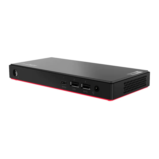
Page 36: Front
(3.2 Gen 2) connector • Connect to USB-C accessories to help expand your computer functionality. To purchase USB-C accessories, go to https://www.lenovo.com/accessories Connect USB-compatible devices, such as a USB keyboard, USB mouse, USB 4. USB 2.0 connector storage device, or USB printer. -
Page 37: Rear
– USB-C to DP: 3840 x 2160 pixels, 60 Hz • Connect to USB-C accessories to help expand your computer functionality. To purchase USB-C accessories, go to https://www.lenovo.com/accessories Connect USB-compatible devices, such as a USB keyboard, USB mouse, USB 5. USB 2.0 connector storage device, or USB printer. -
Page 38: Bottom
Bottom Fan models Fanless models Connect the matched DIN rail bracket, power adapter bracket, or VESA mount bracket with the matched screws (M3 x 4 mm x 3 pcs) when you install the ® 1. VESA threaded holes computer on a wall. ThinkCentre M75nHardware Maintenance Manual... -
Page 39: Chapter 4. Service Checkout And Symptom-To-Fru Index
• Machine type and model • Processor or hard disk drive upgrades • Failure symptom – Do diagnostics indicate a failure? – What, when, where, single, or multiple systems? – Is the failure repeatable? – Has this configuration ever worked? © Copyright Lenovo 2020... -
Page 40: Symptom-To-Fru Index
– If it has been working, what changes were made prior to its failing? – Is this the original reported failure? • Diagnostics version – Type and version level • Hardware configuration – Print (print screen) configuration currently in use –... -
Page 41: Power Supply Problems
Error FRU/Action The boot sector on the startup drive is corrupted. The drive must be formatted. Do the following: 1. Attempt to back up the data on the failing hard disk drive. 2. Using the operating system programs, format the hard disk drive. -
Page 42: Post Error Codes
POST error codes Each time you turn on the system, it performs a series of tests that check the operation of the system and some options. This series of tests are called the Power-On Self-Test, or POST. POST checks the following operations: •... -
Page 43: Miscellaneous Error Conditions
8998 Not enough shadow RAM resources This error message is displayed for OPTION ROM, not all devices when the shadow RAM resources initialized. Suggest to remove some for option ROM are insufficient. add-on cards, or change to UEFI If the legacy option ROM is mode in BIOS setup. - Page 44 Message/Symptom FRU/Action Incorrect memory size during POST 1. Run the Memory tests. 2. Memory Module 3. System Board "Insert a Diskette" icon appears with a known-good 1. System Board diagnostics diskette in the first 3.5-inch diskette drive. 2. Diskette Drive Cable 3.
-
Page 45: Undetermined Problems
Message/Symptom FRU/Action Serial or parallel connector device failure (adapter 1. External Device Self-Test OK? connector) 2. External Device 3. Cable 4. Alternate Adapter 5. System Board Some or all keys on the keyboard do not work 1. Keyboard 2. Keyboard Cable 3. - Page 46 ThinkCentre M75nHardware Maintenance Manual...
-
Page 47: Chapter 5. Troubleshooting, Diagnostics, And Recovery
4. Run the diagnostic program. See “Diagnostics” on page 49. 5. Recover your operating system. See “Recovery” on page 50. 6. If the problem persists, contact Lenovo. Troubleshooting Use the troubleshooting information to find solutions to problems that have definite symptoms. -
Page 48: Startup Problems
Startup problems Problem Solution • Ensure that the power cord is correctly connected to the rear of the computer and to a working electrical outlet. • If the computer has a secondary power switch on the rear of the The computer does not start up when you computer, ensure that it is switched on. -
Page 49: Audio Problems
Audio problems Problem Solution • If you are using powered external speakers that have an On/Off control, ensure that: – The On/Off control is set to the On position. – The speaker power cable is connected to a properly grounded, functional ac electrical outlet. - Page 50 Problem Solution • Connect the cable from the Ethernet connector to the RJ45 connector of the hub. • Enable the Ethernet LAN feature in UEFI BIOS. • Enable the Ethernet LAN adapter. 1. Go to Control Panel and view by large icons or small icons. 2.
- Page 51 Problem Solution • Enable the Bluetooth feature in UEFI BIOS. • Enable all Bluetooth devices. 1. Right-click the Start button to open the Start context menu. 2. Click Device Manager. Type the administrator password or provide confirmation if prompted. 3. Expand Bluetooth to display all Bluetooth devices. Right-click each Bluetooth device, and then click Enable device.
-
Page 52: Performance Problems
Performance problems Problem Solution Note: Depending on the volume of the storage drives and amount of data stored on the storage drives, the disk-defragmentation process might take up to several hours. 1. Close any open programs and windows. 2. Open the Start menu. Excessive fragmented files exist on the 3. -
Page 53: Storage Drive Problems
Storage drive problems Problem Solution • Ensure that the signal cables and power cables for all the storage drives are connected correctly. • Ensure that the computer is configured correctly to support the storage drives. Some or all storage drives are missing from –... -
Page 54: Serial Connector Problems
Problem Solution • Disable any background programs, such as AntiVirus or Desktop The playback is slow or choppy. Themes. • Ensure that video resolution is less than 1152 x 864 pixels. • Ensure that the disc is in the drive with the shiny side of the disc facing down. -
Page 55: Software Problems
Use diagnostic solutions to test hardware components and report operating-system-controlled settings that interfere with the correct operation of your computer. Lenovo diagnostic tools For information about Lenovo diagnostic tools, go to: https://pcsupport.lenovo.com/lenovodiagnosticsolutions UEFI diagnostic program A UEFI diagnostic program is preinstalled on the computer. It enables you to test memory modules and internal storage devices, view system information, and check and recover bad sectors on internal storage devices. -
Page 56: Recovery
Table 1. Options on the main screen of the UEFI diagnostic program DIAGNOSTICS TOOLS • CPU [U] • SYSTEM INFORMATION [F1] • DISPLAY [D] • BAD BLOCK RECOVERY [F3] • KEYBOARD [K] • SMART INFORMATION [F5] • MEMORY [E] • MOTHERBOARD [H] •... -
Page 57: Windows Automatic Recovery
Windows recovery programs are damaged. If you did not create a recovery USB drive as a precautionary measure, you can contact Lenovo Customer Support Center and purchase one from Lenovo. For a list of the Lenovo Support phone numbers for your country or region, go to: https://pcsupport.lenovo.com/supportphonelist Create a recovery USB drive Attention: The creation process deletes anything stored on the USB drive. - Page 58 • From Lenovo Vantage: Open Lenovo Vantage to check the available update packages. If the latest UEFI BIOS update package is available, follow the on-screen instructions to download and install the package. • From the Lenovo Support Web site: Go to and select the entry for your computer.
-
Page 59: Chapter 6. Hardware Removal And Installation
Common tool Isolated tweezers Common tool Hexagonal socket Common tool Silicone grease Consumable tool Polyamide tape Consumable tool Mylar tape Consumable tool Eraser Consumable tool Electrical tape Consumable tool Double-sided tape Consumable tool Conductive tape Consumable tool © Copyright Lenovo 2020... -
Page 60: Major Frus And Crus (Fan Models)
Note: The silicone grease can be applied to the surfaces of the microprocessor and heat sink to eliminate air gaps. The hexagonal socket is used to pick up the antenna connectors. Major FRUs and CRUs (fan models) Your computer contains the following types of CRUs and FRUs: •... -
Page 61: Major Frus And Crus (Fanless Models)
Rear Wi-Fi antenna* Rear I/O bracket For detailed FRU and CRU information, such as the FRU part numbers and supported computer models, go http://www.lenovo.com/serviceparts-lookup Major FRUs and CRUs (fanless models) Your computer contains the following types of CRUs and FRUs: •... - Page 62 Number Description Self-service CRU Optional-service CRU Bottom cover Thermal pad Chassis Wi-Fi card* M.2 solid-state drive Coin-cell battery Heat sink Right cover Wall mount* Power adapter* Power cord* ThinkCentre M75nHardware Maintenance Manual...
- Page 63 Rear Wi-Fi antenna cable* Rear Wi-Fi antenna* System board Heat sink cover* * for selected models For detailed FRU and CRU information, such as the FRU part numbers and supported computer models, go http://www.lenovo.com/serviceparts-lookup Chapter 6 Hardware removal and installation...
-
Page 64: System Board
System board Fan models Microprocessor fan connector Coin-cell battery connector Internal speaker connector Clear CMOS (Complementary Metal Oxide Semiconductor) / Recovery jumper M.2 solid-state drive slot 1 M.2 solid-state drive slot 2 (M.2 SATA solid-state drive compatible) Wi-Fi card slot Cover presence switch connector (intrusion switch connector) ThinkCentre M75nHardware Maintenance Manual... -
Page 65: Removing And Installing Hardware (Fan Models)
Fanless models Coin-cell battery connector Clear CMOS (Complementary Metal Oxide Semiconductor) / Recovery jumper M.2 solid-state drive slot 1 4G/5G LTE slot Internal speaker connector M.2 solid-state drive slot 2 (for M.2 SATA solid-state drive only) Wi-Fi card slot Cover presence switch connector (intrusion switch connector) Removing and installing hardware (fan models) This section provides instructions on how to remove and install hardware for your computer. -
Page 66: Power Adapter And Power Cord
Power adapter and power cord Prerequisite Before you start, read Chapter 1 “Important safety information” on page 1 and print the following instructions. Replacement procedure 1. Remove any media from the drives and turn off all connected devices and the computer. 2. -
Page 67: Din Rail Bracket Kit
5. Install the power cord. 6. Install the power adapter. 7. Reconnect the external cables to the corresponding connectors on the computer, and then reconnect the power cord to the electrical outlet. DIN rail bracket kit Note: The DIN rail bracket kit is available only on some models. Prerequisite Before you start, read Chapter 1 “Important safety information”... - Page 68 3. Remove the computer with the DIN rail bracket from the rail. 4. Turn over the computer so that the bottom cover is facing up. Then, remove the DIN rail bracket. 5. Install the DIN rail bracket. ThinkCentre M75nHardware Maintenance Manual...
-
Page 69: Power Adapter Bracket Kit
6. If you have not installed the rail, install it to a place where you want to mount the computer. 7. Install the computer with the DIN rail bracket to the rail. 8. Reconnect the external cables to the corresponding connectors on the computer, and then reconnect the power cord to the electrical outlet. - Page 70 Prerequisite Before you start, read Chapter 1 “Important safety information” on page 1 and print the following instructions. Replacement procedure 1. Remove any media from the drives and turn off all connected devices and the computer. 2. Disconnect the power cord from the electrical outlet and disconnect all cables from the computer. 3.
- Page 71 6. Remove the power adapter from the power adapter bracket. 7. Turn over the computer so that the bottom cover is facing up. 8. Remove the power adapter bracket from the computer. 9. Install the power adapter bracket to the computer. 10.
- Page 72 11. Install the power adapter into the power adapter bracket. 12. Install the power cord to the power adapter. See “Power adapter and power cord” on page 60. 13. Install the power adapter bracket to the wall mount bracket. 14. Install the screw to secure the power adapter bracket to the wall mount bracket. 15.
-
Page 73: Vesa Mount Bracket Kit
VESA mount bracket kit Note: The VESA mount bracket kit is available only on some models. Prerequisite Before you start, read Chapter 1 “Important safety information” on page 1 and print the following instructions. Replacement procedure 1. Remove any media from the drives and turn off all connected devices and the computer. 2. -
Page 74: Rear Wi-Fi Antenna
7. Install the VESA mount bracket to the computer. 8. Install the VESA mount bracket to the wall mount bracket. 9. Install the screw to secure the VESA mount bracket to the wall mount bracket. 10. Reconnect the external cables and power adapter to the corresponding connectors on the computer, and then reconnect the power cord to the electrical outlet. -
Page 75: Bottom Cover
Replacement procedure 1. Remove any media from the drives and turn off all connected devices and the computer. 2. Disconnect the power cord from the electrical outlet and disconnect all cables from the computer. 3. Remove the rear Wi-Fi antenna. 4. - Page 76 Before you open the bottom cover, turn off the computer and wait several minutes until the computer is cool. Replacement procedure 1. Remove any media from the drives and turn off all connected devices and the computer. 2. Disconnect the power cord from the electrical outlet and disconnect all cables from the computer. 3.
-
Page 77: Wi-Fi Card
11. Reconnect the external cables and power adapter to the corresponding connectors on the computer, and then reconnect the power cord to the electrical outlet. Wi-Fi card Note: The Wi-Fi card and Wi-Fi antenna cables are available only on some models. Prerequisite Before you start, read Chapter 1 “Important safety information”... -
Page 78: M.2 Solid-State Drive
M.2 solid-state drive Prerequisite Before you start, read Chapter 1 “Important safety information” on page 1 and print the following instructions. Replacement procedure 1. Turn over the computer so that the bottom cover is facing up. 2. Remove the bottom cover. See “Bottom cover” on page 69. 3. -
Page 79: Computer Cover And Rear I/O Bracket
Computer cover and rear I/O bracket Prerequisite Before you start, read Chapter 1 “Important safety information” on page 1 and print the following instructions. Replacement procedure 1. Turn over the computer so that the bottom cover is facing up. 2. Remove the bottom cover. See “Bottom cover” on page 69. 3. - Page 80 7. Remove the computer cover from the rear I/O bracket. 8. Insert the retaining latches on the computer cover into the corresponding holes in the rear I/O bracket. 9. Install the computer cover to the rear I/O bracket. 10. Turn over the computer cover and the rear I/O bracket so that the computer cover is facing up. ThinkCentre M75nHardware Maintenance Manual...
-
Page 81: Coin-Cell Battery
11. Install the computer cover and the rear I/O bracket to the chassis. 12. Reinstall the removed parts. Then, reconnect the power adapter and all disconnected cables to the computer. 13. Turn over the computer so that the bottom cover is facing down. Coin-cell battery Prerequisite Before you start, read Chapter 1 “Important safety information”... -
Page 82: System Fan
7. Install the coin-cell battery. 8. Route the coin-cell battery cable under the system fan and connect the cable to the coin-cell battery connector on the system board. See “System board” on page 58. 9. Reinstall the removed parts. Then, reconnect the power adapter and all disconnected cables to the computer. -
Page 83: Internal Speaker
7. Install the system fan. 8. Connect the system fan cable to the microprocessor fan connector on the system board. See “System board” on page 58. 9. Reinstall the removed parts. Then, reconnect the power adapter and all disconnected cables to the computer. -
Page 84: Heat Sink
7. Install the internal speaker. 8. Connect the internal speaker cable to the internal speaker connector on the system board. See “System board” on page 58. 9. Reinstall the removed parts. Then, reconnect the power adapter and all disconnected cables to the computer. -
Page 85: System Board
7. Remove the heat sink. 8. Install the heat sink. 9. Reinstall the removed parts. Then, reconnect the power adapter and all disconnected cables to the computer. 10. Turn over the computer so that the bottom cover is facing down. System board Prerequisite Before you start, read Chapter 1 “Important safety information”... - Page 86 2. To get access to the system board, remove the following parts if any: a. “Wi-Fi card” on page 71. b. “M.2 solid-state drive” on page 72. c. “Computer cover and rear I/O bracket” on page 73. d. “Coin-cell battery” on page 75. e.
-
Page 87: Front Wi-Fi Antenna And Cable
6. Reinstall all parts that you have removed one by one in the reversed sequence as you remove them. Refer to the information that you have noted down and the related topics in “Removing and installing hardware (fan models)” on page 59. 7. -
Page 88: Rear Wi-Fi Antenna Cable
5. Install the front Wi-Fi antenna and cable. Secure the front and rear Wi-Fi antenna cables with tapes. 6. Reinstall all parts that you have removed one by one in the reversed sequence as you remove them. Then, reconnect the power adapter and all disconnected cables to the computer. 7. -
Page 89: Removing And Installing Hardware (Fanless Models)
5. Peel off the tapes that secure the front and rear Wi-Fi antenna cables. Remove the rear Wi-Fi antenna cable. 6. Install the rear Wi-Fi antenna cable. Secure the front and rear Wi-Fi antenna cables with tapes. 7. Reinstall all parts that you have removed one by one in the reversed sequence as you remove them. Then, reconnect the power adapter and all disconnected cables to the computer. -
Page 90: External Options
External options You can connect external options to your computer, such as external speakers, a printer, or a scanner. For some external options, you must install additional software in addition to making the physical connection. When installing an external option, see Chapter 3 “Product overview” on page 29 to identify the required connector. - Page 91 4. Remove the power cord. 5. Install the power cord. 6. Install the power adapter. Chapter 6 Hardware removal and installation...
-
Page 92: Heat Sink Cover
7. Reconnect the external cables to the corresponding connectors on the computer, and then reconnect the power cord to the electrical outlet. Heat sink cover Note: The heat sink cover is available only on some models. Prerequisite Before you start, read Chapter 1 “Important safety information” on page 1 and print the following instructions. -
Page 93: Din Rail Bracket Kit
DIN rail bracket kit Note: The DIN rail bracket kit is available only on some models. Prerequisite Before you start, read Chapter 1 “Important safety information” on page 1 and print the following instructions. Avoid contact with the hot computer. During operation, the computer becomes hot enough to burn the skin. Before you touch the computer, turn off the computer, disconnect power, and wait approximately 30 minutes for the computer to cool. - Page 94 6. Install the DIN rail bracket. 7. Reinstall all removed parts. 8. If you have not installed the rail, install it to a place where you want to mount the computer. ThinkCentre M75nHardware Maintenance Manual...
-
Page 95: Power Adapter Bracket Kit
9. Install the computer with the DIN rail bracket to the rail. 10. Reconnect the external cables to the corresponding connectors on the computer, and then reconnect the power cord to the electrical outlet. Power adapter bracket kit Note: The power adapter bracket kit is available only on some models. Prerequisite Before you start, read Chapter 1 “Important safety information”... - Page 96 4. Remove the screw that secures the power adapter bracket to the wall mount bracket. 5. Remove the power adapter bracket from the wall mount bracket. 6. Remove the power cord from the power adapter. See “Power adapter and power cord” on page 84. 7.
- Page 97 9. Remove the power adapter bracket from the computer. 10. Install the power adapter bracket to the computer. 11. Turn over the computer so that the bottom cover is facing down. 12. Install the power adapter into the power adapter bracket. 13.
-
Page 98: Vesa Mount Bracket Kit
14. Install the power adapter bracket to the wall mount bracket. 15. Install the screw to secure the power adapter bracket to the wall mount bracket. 16. Reinstall all removed parts, if any. 17. Reconnect the external cables and power adapter to the corresponding connectors on the computer, and then reconnect the power cord to the electrical outlet. - Page 99 2. Disconnect the power cord from the electrical outlet and disconnect all cables from the computer. 3. Remove the heat sink cover, if any. See “Heat sink cover” on page 86. 4. Remove the screw that secures the VESA mount bracket. 5.
-
Page 100: I/O Box
8. Install the VESA mount bracket to the computer. 9. Install the VESA mount bracket to the wall mount bracket. 10. Install the screw to secure the VESA mount bracket to the wall mount bracket. 11. Reinstall all removed parts, if any. 12. - Page 101 • After you install the I/O box to the computer, you can still mount the I/O box and the computer together to the wall by using a matched DIN rail bracket kit or a VESA mount bracket kit. For details, see “DIN rail bracket kit”...
-
Page 102: Rear Wi-Fi Antenna
6. Install a new I/O box. Then, install the USB-C adapter. 7. Turn over the computer and the I/O box together so that the computer is on top. 8. Reinstall all removed parts, if any. Then, reconnect the power cord and all disconnected cables to the computer and the I/O box. -
Page 103: Bottom Cover
3. Remove the rear Wi-Fi antenna. 4. Install the rear Wi-Fi antenna. 5. Reconnect the external cables and power adapter to the corresponding connectors on the computer, and then reconnect the power cord to the electrical outlet. Bottom cover Prerequisite Before you start, read Chapter 1 “Important safety information”... -
Page 104: Wi-Fi Card
Avoid contact with the hot computer. During operation, the computer becomes hot enough to burn the skin. Before you touch the computer, turn off the computer, disconnect power, and wait approximately 30 minutes for the computer to cool. Replacement procedure 1. - Page 105 Avoid contact with the hot computer. During operation, the computer becomes hot enough to burn the skin. Before you touch the computer, turn off the computer, disconnect power, and wait approximately 30 minutes for the computer to cool. Replacement procedure 1.
-
Page 106: M.2 Solid-State Drives
M.2 solid-state drives Prerequisite Before you start, read Chapter 1 “Important safety information” on page 1 and print the following instructions. Avoid contact with the hot computer. During operation, the computer becomes hot enough to burn the skin. Before you touch the computer, turn off the computer, disconnect power, and wait approximately 30 minutes for the computer to cool. -
Page 107: System Board And Coin-Cell Battery
4. Install an M.2 solid-state drive. For more information about the corresponding slot for the M.2 solid-state drive, see “System board” on page 58. Cover the M.2 solid-state drive with a thermal pad if you have removed one. 5. Reinstall all removed parts. Turn over the computer so that the bottom cover is facing down. 6. - Page 108 6. Remove the system board. Note: Carefully handle the system board by its edges. 7. Turn over the system board so that the coin-cell battery is facing up. 8. Remove the coin-cell battery. 9. Install the new coin-cell battery on the new system board. 10.
-
Page 109: Left Cover And Front Antenna Cable
11. Route the internal speaker cable and front antenna cable by the cable clip, and install the system board. 12. Reinstall all parts that you have removed one by one in the reversed sequence as you remove them. Refer to the information that you have noted down and the related topics in “Removing and installing hardware (fanless models)”... - Page 110 6. Remove the left cover. 7. Remove the front antenna cable. 8. Install the front antenna cable. ThinkCentre M75nHardware Maintenance Manual...
-
Page 111: Right Cover
9. Route the front antenna cable by the cable clip, and install the left cover. 10. Reinstall all removed parts. Turn over the computer so that the bottom cover is facing down. Then, reconnect the power adapter and all disconnected cables to the computer. Right cover Prerequisite Before you start, read Chapter 1 “Important safety information”... -
Page 112: Internal Speaker
6. Remove the right cover. 7. Install the right cover. 8. Reinstall all removed parts. Turn over the computer so that the bottom cover is facing down. Then, reconnect the power adapter and all disconnected cables to the computer. Internal speaker Prerequisite Before you start, read Chapter 1 “Important safety information”... -
Page 113: Rear Antenna Cable
2. Remove the bottom cover. See “Bottom cover” on page 97. 3. Remove the M.2 solid-state drives. See “M.2 solid-state drives” on page 100. 4. Remove the Wi-Fi card. See “Wi-Fi card” on page 98. 5. Remove the system board. See “System board and coin-cell battery” on page 101. 6. -
Page 114: Heat Sink
2. Turn over the computer so that the bottom cover is facing up. 3. Remove the bottom cover. See “Bottom cover” on page 97. 4. Remove the M.2 solid-state drives. See “M.2 solid-state drives” on page 100. 5. Remove the Wi-Fi card. See “Wi-Fi card” on page 98. 6. - Page 115 Avoid contact with the hot computer. During operation, the computer becomes hot enough to burn the skin. Before you touch the computer, turn off the computer, disconnect power, and wait approximately 30 minutes for the computer to cool. Replacement procedure 1.
- Page 116 ThinkCentre M75nHardware Maintenance Manual...
-
Page 117: Notices And Trademarks
Lenovo representative for information on the products and services currently available in your area. Any reference to a Lenovo product, program, or service is not intended to state or imply that only that Lenovo product, program, or service may be used. Any functionally equivalent product, program, or service that does not infringe any Lenovo intellectual property right may be used instead. - Page 118 Actual results may vary. Users of this document should verify the applicable data for their specific environment. This document is copyrighted by Lenovo and is not covered by any open source license, including any Linux agreement(s) which may accompany software included with this product. Lenovo may update this document at any time without notice.
Need help?
Do you have a question about the ThinkCentre M75n and is the answer not in the manual?
Questions and answers