Table of Contents
Advertisement
Quick Links
Advertisement
Table of Contents

Related Manuals for CR-Tec CR-LASER SUPER-1

Summary of Contents for CR-Tec CR-LASER SUPER-1
- Page 1 Version: 2.0 This manual contains important laser system safety and operation information. Read and understand all instructions prior to powering on laser unit the first time, to avoid laser eye injury and to avoid breaking the law. Keep this manual in a safe place for future reference.
- Page 2 USER MANUAL WARNING DATA Lasers can be hazardous and have unique safety considerations. Permanent eye injury and blindness is possible if lasers are used incorrectly. Pay close attention to each safety REMARK and WARNING statement in the user manual. Read all instructions carefully BEFORE operating this device.
-
Page 3: Laser Safety Warnings
USER MANUAL LASER SAFETY WARNINGS Potential laser injury hazard exists with this product! Read these instructions carefully, which includes important information about installation, safe use and service! Caution: Avoid direct eye contact with laser light. Never intentionally expose your eyes or others to direct laser light. - Page 4 USER MANUAL LASER SAFETY AND OPERATING INSTRUCTIONS STOP AND READ ALL LASER SAFETY DATA Laser light is different from any other light source with which you may be familiar. The light from this product can potentially cause eye injury if not set up and used properly.
- Page 5 USER MANUAL Never point a laser at aircraft, this is a federal offense. Never point un-terminated laser beams into the sky. Do not expose the output optic (aperture) to cleaning chemicals. Do not use laser if the laser appears to be emitting only one or two beams. Do not use laser if housing is damaged or open, or if optics appear damaged in any way.
-
Page 6: Laser Exposure Warning
USER MANUAL LASER EXPOSURE WARNING LASER LIGHT AVOID DIRECT EYE EXPOSURE Further guidelines and safety programs for safe use of lasers can be found in the ANSI Z136.1 Standard “For Safe Use of Lasers”, available from “www.laserinstitute.org”. Many local governments, corporations, agencies, military and others, require all lasers to be used under the guidelines of ANSI Z136.1. -
Page 7: General Safety Instructions
USER MANUAL GENERAL SAFETY INSTRUCTIONS Every person involved with installation and maintenance of this device has to: Be qualified Follow the instructions of this manual CAUTION! Be careful with your operations. With a high voltage you can suffer a dangerous electric shock when touching the wires! This device has left out premises in absolutely perfect condition. - Page 8 USER MANUAL Do not switch the fixture on and off in short intervals as this would reduce the laser diode life. For replacement, please use fuses of same type and rating only. If the device has been exposed to drastic temperature fluctuation, do not switch it on immediately.
-
Page 9: Before Operation
USER MANUAL BEFORE OPERATION Unpacking Instructions CAUTION! Immediately upon receiving a fixture, carefully unpack the carton, check the contents to ensure that all parts are present, and have been received in good condition. Notify the shipper immediately and retain packing material for inspection if any parts appear damage from shipping or the package itself shows signs of mishandling. - Page 10 USER MANUAL The unit is supplied with a power plug appropriate to its voltage and destination. Should any other connections be required they must be carried out with the following configuration. Cable(EU) Cable(US) International Brown Black Live Light blue White Neutral Yellow/Green Green...
- Page 11 USER MANUAL Building a serial DMX-chain If you are using the standard DMX-controllers, you can connect the DMX-output of the controller directly with the DMX-input of the first fixture in the DMX-chain. If you wish to connect DMX-controllers with other XLR-outputs, you need to use adapter cables.
- Page 12 USER MANUAL Proper Laser Set Up & Usage This fixture has been designed to be hung. It is recommended for safety purposes, your lighting effect are properly mounted using a suitable hanging clamp and safety cable. Items appropriate for safe and effective mounting are easily sourced from your lighting vendor.
- Page 13 USER MANUAL The installation of the fixture has to be built and constructed in a way that it can hold 10 times the weight for 1 hour without any harming deformation. The installation must always be secured with a secondary safety attachment, e.g.
-
Page 14: Roduct Overview
USER MANUAL RODUCT OVERVIEW Rear Panel NAME FUNCTION Switch Switch on and off the power With socket and integrated fuse holder Mains input DMX output 3PIN Female XLR port,using for DMX DMX input 3PIN Male XLR port, using for DMX Switch off the laser manually if error occurs Urgent and safe switch Key switch... - Page 15 USER MANUAL ILDA / Hardware Setting Panel NAME FUNCTION X SIZE The Size of X / Y axis adjustment Y SIZE X MIRROR X / Y axis mirror setting (It could be done by Y MIRROR LCD control panel as well) Microphone.
-
Page 16: Warning Label
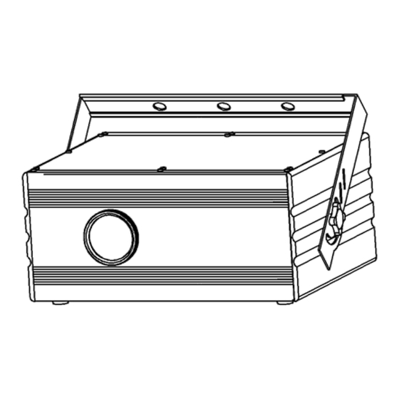
USER MANUAL Front Panel NAME FUNCTION POWER Indicates that the unit is switched on. DMX connection indicated LED. Red is DMX connected, Green is preprogram standalone mode. Flashes to the sound of the music MUSIC detected by the mic Laser output Laser output aperture. -
Page 17: Control & Function
USER MANUAL IMPORTANT For your own safety and full laser safety regulation, we do strongly recommend you to take this optional switch! CONTROL & FUNCTION Regular breaks during operation are essential to maximize the life of this device as it is not designed for continual use. Do not switch the unit on and off in short time intervals Always unplug the unit when it is not used for a longer time. - Page 18 USER MANUAL Operation Stand Alone Preprogram Laser Show Press FUNC to enter MODE OPTION. Till to LED panel show any one of “A1, A2, S1 , S2”. Press UP or DOWN to select your favorite Stand Alone mode as above. Press ENTER to confirm the setting.
-
Page 19: Dmx Mode
USER MANUAL DISPLAY STAND ALONE MODE LASER EFFECT Auto laser show with random order Auto laser show with traditional order Sound activated laser show with random order Sound activated laser show with traditional order Attention: In S1 or S2 MODE (Sound Activated Mode), the laser will be blocked out in 3 second when MIC Signal was not detected. - Page 20 USER MANUAL PATTERN MIRROR REVERSE SETTING Press FUNC to enter MODE OPTION Till to LED panel show any one of Press UP or DOWN to select pattern mirror mode as above. Press ENTER to confirm the setting. In the MODE OPTION setting, the pattern mirror mode that you are going to choose is flashing.
- Page 21 USER MANUAL ILDA Control Mode This unit has the ILDA DB25 port, and it can be controlled by the PC, There is auto transform set in the inside of the unit to transform the ILDA and preprogrammed show. when connecting with the 25 pin cable, the unit will be control by PC, when disconnect the unit, it will be preprogrammed program control。...
- Page 22 USER MANUAL DMX GOBO MODE CHANNEL VALUE DESCRIPTION CH 2 000-255 8 Group GROUP CH 3 000-255 16 Patterns in each group PATTERN CH 4 Color channel is not activated in single color laser COLOR Full pattern without clipping CH 5 001-127 0%~99% fixed pattern clipped CLIPING...
- Page 23 USER MANUAL 000-127 0 -359 degree fixed Z axis rolled CH 12 128-191 Clockwise rolling Z AXIS ROLLING 192-255 Anticlockwise rolling CH 13 0-255 Slow to fast ROLLSPEED 000-127 128 different fixed position on X axis CH 14 128-191 Clockwise moving X AXIS MOVING 192-255...
-
Page 24: Pattern List
USER MANUAL PATTERN LIST Numbe tunnel pole curve line text graphic 000-015 016-031 032-047 048-063 064-079 080-095 096-111 112-127 128-143 144-159 160-175 176-191 192-207 208-223 224-239 240-255... -
Page 25: Maintenance
USER MANUAL MAINTENANCE Make sure the area below the installation place is free from unwanted persons during servicing Switch off the fixture, unplug the mains cable and wait until the unit has been cooled down. Housings, fixations and installations spots( ceiling, truss, suspensions) should be totally free from any deformation The mains cables must be in impeccable condition and should be replaced immediately when even a small problem is detected... - Page 26 USER MANUAL The fixture is power on, but no laser coming out from aperture. Check the laser aperture cover. Check the key switch. Check the remote interlock or interlock connector. Wait for at least 30 minutes to warm up in low temperature. Check whether it is in music mode without sound signal.
- Page 27 USER MANUAL SPECIFICTAIONS Mains Input: AC100~240V, 50/60Hz Fuse: 250V 2A Slow Blow (20mm Glass) Total Power: X/Y Axis Beam Angle: ±25° Control Mode: Auto, Sound, DMX, Slave, ILDA Laser Power: 100mW 532nm Green CW Laser Classification: Class 3B Laser Safety Standard: EN60825-1 2007 Condition Temperature: 10~40℃...
Need help?
Do you have a question about the CR-LASER SUPER-1 and is the answer not in the manual?
Questions and answers