
Related Manuals for Simco-Ion Chargemaster VCM Series

Summary of Contents for Simco-Ion Chargemaster VCM Series
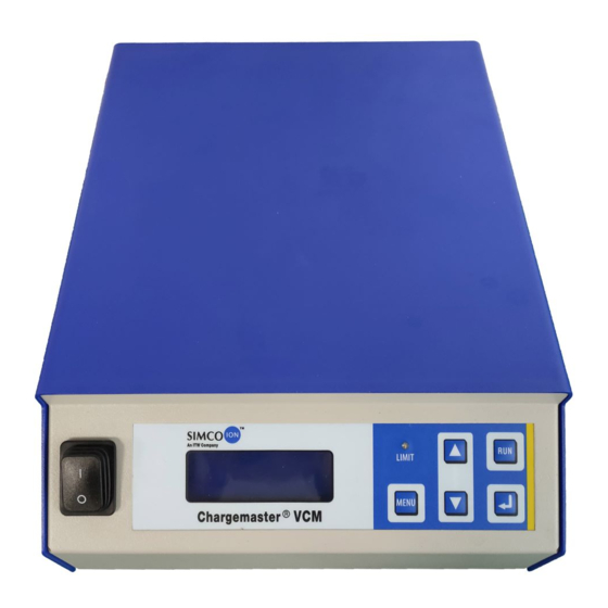
- Page 1 Chargemaster VCM30 and VCM60 Electrostatic Generating Power Supplies INSTALLATION AND OPERATING INSTRUCTIONS C HARGEMAS TER VC M 52 0 10 67 R ev. B...
-
Page 2: Table Of Contents
TABLE OF CONTENTS 1. DESCRIPTION ...................... 3 2. SAFETY ....................... 3 3. FEATURES ......................4 4. SPECIFICATIONS ....................5 5. INSTALLATION ....................7 6. OPERATION ....................... 12 7. REMOTE OPERATION ..................18 8. MAINTENANCE ....................23 9. REPLACEMENT PARTS ..................25 10. -
Page 3: Description
1. DESCRIPTION Each Chargemaster VCM Electrostatic Generating Power Supply incorporates high frequency switch-mode and power factor corrected technology within a compact enclosure. Each unit is electronically current limited and arc protected. The output voltage is adjustable from zero to full rated output at maximum rated current. -
Page 4: Features
3. FEATURES Operates in either Current Control or Voltage Control mode. • Front panel orientation is factory selectable for bench top or wall • mounting. Flat panel with membrane switches. • Mounting brackets for bottom or top mounting. • No cooling fan. •... -
Page 5: Specifications
AC Input Voltage: 85 - 264 V AC Input Frequency: 47-63 Hz Fuse (Rear Panel): 3.15 AT Output Connections: 4 Output Ports (Simco-Ion SLCC type) Remote Control Connection: 25 Pin D-Sub Connector Cooling: Convection Polarity: N = Negative, P = Positive Short-Circuit Protection: Output Electronically Protected at Max. - Page 6 STANDARD CHARGEMASTER VCM VCM30-N, (Negative) P/N: 4012555 VCM30-P, (Positive) P/N: 4012557 VCM60-N, (Negative) P/N: 4012559 VCM60-P, (Positive) P/N: 4012561 DUAL POLARITY CONFIGURATION Reversing the mounting brackets on the bottom power supply allows two standard VCM units to be stacked together. Units are supplied with mounting brackets and hardware to affix the brackets to the power...
-
Page 7: Installation
Carefully remove equipment from the carton and inspect the contents. NOTE – If any damage has occurred during shipment, notify the local carrier at once. A report should also be forwarded to Simco-Ion, 2257 North Penn Road, Hatfield PA 19440. See Section 9 (Warranty) for Return Shipment information. - Page 8 c) Attach two mounting brackets, (see Figure 2), to the VCM with M4 x 8 screws (provided in kit). Use mounting bracket as a template to mark the two mounting hole locations. Drill two 0.201” diameter clearance holes at marked locations. f) Position mounting bracket’s screw holes directly above drilled holes.
- Page 9 Connecting a Chargemaster HV Power Supply to a bar or applicator not manufactured by Simco-Ion for use with that model of power supply, without the written permission of Simco-Ion, will void the power supply’s warranty. A TETRA Charging Bar (see Figure 3) will be used in this manual for purposes of illustrating the three most common installation options for charging bars and applicators.
- Page 10 Option 1 – Charging Bar with Grounded Surface This application illustrates the use of a TETRA bar facing a grounded surface. The material to be charged should rest on the grounded surface. In the example shown in Figure 4, the charging bar is located facing an empty core in a roll- to-roll changeover application.
- Page 11 Chargemaster VCM Power Supplies are designed to power the approved Simco-Ion charging bars Figure 7 applicators identified in Section 4. The Remote On/Off function should be used to cycle the power supply On and Off whenever possible.
-
Page 12: Operation
6. OPERATION CAUTION – Electrical Shock Hazard Do not touch Charging Bar during operation. CAUTION – Fire Hazard Do not operate equipment in close proximity to any flammable solvents or flammable materials. 6.1 Turning On/Off a) Turn power switch on front panel to OFF (“O”) position. b) Ensure power supply GROUND TERMINAL is properly grounded. - Page 13 Time remaining before the bar is scheduled to be cleaned 6.3 Operating Modes Simco-Ion’s Chargemaster VCM Electrostatic Generating Power Supplies can be run in either Constant Current or Constant Voltage mode. Select the mode that is best for your application:...
- Page 14 Simco-Ion Chargemaster power supplies. 6.4 Navigating the Menus Enter one of the two available menus by pressing [MENU] to enter the “Control Menu”, or pressing [MENU + ENTER] to enter the “Service Menu”. Navigating through menu items is done by pressing [MENU].
- Page 15 6.6 Service Menu Structure Menu Item Possible Values Resolution Default Disable Remote Set Point Disable Enable Disable Remote On-Off Control Disable Enable 0.0 to 5.0 Sec Readout Stretched 0.1 Sec 0.7 Seconds (Range) 0.5 to 5.0 Sec Limited Stretched 0.1 Sec 0.7 Seconds (Range) 10 to 500 mSec...
- Page 16 6.7 Summary of Buttons and Their Functions a) [Menu]: Go to the “Control Menu” or select the next menu item. b) [Up]: Set the HV set-point or increase a menu item value. c) [Down]: Set the HV set-point or decrease a menu item value d) [Run]: Override the HV output in Remote mode.
- Page 17 6.10 Clean Bar Timer The Clean Bar Timer monitors the time that the high voltage output is present, and counts down from a preset cleaning interval. To set the cleaning interval: • Press [MENU + ENTER] for the Service Menu. •...
-
Page 18: Remote Operation
7. REMOTE OPERATIONS Function Function Remote On/Off (+) Remote On/Off (-) Remote Current Set Point Remote Voltage Set Point GND (blue) Remote Voltage Output GND (blue) Remote Current Output +24V Internal Power Supply +12V Internal Power Supply 0V Internal Power Supply Clean Bar (Open Collector) Clean Bar (Open Emitter) Limit Alarm (Open Collector) - Page 19 7.1 Remote Functions Several functions may be controlled remotely through the 25-pin D-Sub connector located on the rear of the unit (the mating D-Sub connector and back shell are supplied in the mounting kit with each unit): • Turning On/Off the High Voltage Output •...
- Page 20 7.3 Controlling the Voltage Set Point Remotely a) The output voltage can be controlled from a remote source that provides any of the following control signals: • 0 - 5 V DC • 0 - 10 V DC • 0 - 20 mA DC •...
- Page 21 • Press [ENTER] to accept the change (asterisk will flash). • Press [MENU + UP] to return to the Main Screen. c) Connect the reference signal to D-Sub connector pins 2 & 15 d) Inputting a high signal will drive the VCM Power Supply to its maximum output;...
- Page 22 7.7 Monitoring the High Voltage On Indicator Remotely a) The High Voltage “On” indicator (lightning bolt symbol “7”) can be monitored externally by an LED or PLC input. An opto-isolated transistor provides the signal; maximum load must not exceed 50VDC / 50mA.
-
Page 23: Maintenance
8. MAINTENANCE NOTE – Only qualified service personnel are to perform maintenance tasks. CAUTION – Electrical Shock Hazard Disconnect power source before performing maintenance tasks. CAUTION – Electrical Shock Hazard When opening the equipment, you may come into contact with parts connected to dangerous voltages. - Page 24 Problem Cause Remedy Specify set point with the [▲]/[▼] buttons or with the proper A set point has not been signal when Remote Voltage specified through the [▲]/[▼] Programming is in use. Disable buttons or the Remote Voltage Remote Voltage Programming Programming is activated function to return to front panel control.
-
Page 25: Replacement Parts
9. REPLACEMENT PARTS Part Number Description 5051259 Mounting Kit • Mounting Brackets, Qty. 2 • 25 Pin D-Sub Connector and Shell, Qty. 1 • Bumper, Rubber, Qty. 4 • Hardware, Mounting Kit, M4x8 Screws, Qty. 4 4100286 SLCC HV Connector Kit (30 kV) •... -
Page 26: Warranty
The equipment being returned under warranty should be shipped by the purchaser to Simco-Ion, 2257 North Penn Road, Hatfield PA 19440, transportation prepaid and insured for its replacement cost. Prior to returning any goods for any reason, contact Simco-Ion Customer Service at (215) 822-6401 for a Return Authorization Number. This number must accompany all returned items. - Page 27 (This page intentionally left blank) C HARGEMAS TER VC M 52 0 10 67 R ev. B...
- Page 28 Simco-Ion 2257 North Penn Road Hatfield, PA 19440 (215) 822-6401 (800) 203-3419 www.simco-ion.com customerservice@simco-ion.com © 2011 Simco-Ion. Printed in the U.S.A. C HARGEMAS TER VC M 52 0 10 67 R ev. B...
Need help?
Do you have a question about the Chargemaster VCM Series and is the answer not in the manual?
Questions and answers