Table of Contents
Advertisement
Advertisement
Table of Contents

Subscribe to Our Youtube Channel
Related Manuals for Wood-mizer SW-10 SETWORKS

Summary of Contents for Wood-mizer SW-10 SETWORKS
- Page 3 SW-10 SETWORKS Operation & Parts Manual LT15/HR115 SW-10 Setworks rev. A1.00 Safety is our #1 concern! Read and understand all safety information and instructions before operating, setting up or maintaining this machine. Form #644...
-
Page 4: Table Of Contents
Storing Programs in the Setworks Memory SECTION 3 TROUBLESHOOTING Setworks Malfunction ................3-1 SECTION 4 REPLACEMENT PARTS How To Use The Parts List ..............4-5 Sample Assembly ...................4-5 Mounting Kit, SW-10 for LT15 ............4-6 SW-10 Setworks for LT15P and LX100 ........4-7 SW-07doc111419 Table of Contents... -
Page 5: Installation
INSTALLATION SW-10 Controller Installation Procedure on the LT15 Sawmills SECTION 1 INSTALLATION SW-10 Controller Installation Procedure on the LT15 Sawmills IMPORTANT! Make sure the sawmill is properly set up before performing setworks installation and/or operation. WARNING! Before performing any service to the sawmill control box panel, turn the key to the “0”. - Page 6 INSTALLATION SW-10 Controller Installation Procedure on the LT15 Sawmills 3. Install the encoder. See Photo 1-1. PHOTO 1-1 4. Route the encoder wire inside the mast to the controller. Connect wires to the encoder terminals according to the table below. Encoder White Yellow...
- Page 7 INSTALLATION SW-10 Controller Installation Procedure on the LT15 Sawmills 5. Connect the wire to the controller according to the table below. Down Feed Yellow Green Up Feed Green Brown Power Supply White Grey Manual control common connection Pink Additional Up Feed Blue Additional Down Feed Short Circuit...
- Page 8 INSTALLATION SW-10 Controller Installation Procedure on the LT15 Sawmills See Photo 1-6. Proper routing of wires to the control panel is shown below. PHOTO 1-6 See Photo 1-7. The photo below shows how wires should be connected to the controller. PHOTO 1-7 SW-10doc111419 INSTALLATION...
- Page 9 INSTALLATION SW-10 Controller Installation Procedure on the LT15 Sawmills 6. Remove the control box cover. Insert the 8-conductor cable from the controller to the control box. (See Photo 1-8.) See Photo 1-8. PHOTO 1-8 INSTALLATION SW-10doc111419...
- Page 10 INSTALLATION SW-10 Controller Installation Procedure on the LT15 Sawmills 7. Connect the wire No. 7 with the white wire and the wire No. 8 with the grey wire in one plug. See Photo: 1-9. LT15 WITH DEBARKER LT15 WITHOUT DEBARKER PHOTO 1-9 SW-10doc111419 INSTALLATION...
- Page 11 INSTALLATION SW-10 Controller Installation Procedure on the LT15 Sawmills Disconnect the wires No.3 from the up/down switch contact. Up/Down Switch Contacts PHOTO 1-10 9. Shorten the wire No. 3. Mount a connector on its end and connect this wire to the green INSTALLATION SW-10doc111419...
- Page 12 INSTALLATION SW-10 Controller Installation Procedure on the LT15 Sawmills E-STOP button contact. PHOTO 1-11 SW-10doc111419 INSTALLATION...
- Page 13 INSTALLATION SW-10 Controller Installation Procedure on the LT15 Sawmills 10. Disconnect the upper wires No. 1 and No. 2 from the up/down switch contacts (see photo 1-12). Connect the wire No. 1 with the yellow wire and the wire No. 2 with the brown wire (see photo 1-13).
- Page 14 INSTALLATION SW-10 Controller Installation Procedure on the LT15 Sawmills PHOTO 1-13 11. Connect the green wire with the wire No. 4 that is connected to the green E-STOP button contact. Green E-STOP Contact PHOTO 1-14 1-10 SW-10doc111419 INSTALLATION...
- Page 15 INSTALLATION SW-10 Controller Installation Procedure on the LT15 Sawmills 12. Branch the pink wire and connect it to the bottom up/down switch contacts. PHOTO 1-15 13. Connect the red and blue wires to the upper up/down switch contacts. PHOTO 1-16 INSTALLATION SW-10doc111419 1-11...
- Page 16 INSTALLATION SW-10 Controller Installation Procedure on the LT15 Sawmills 14. The photo below shows the control panel with finished connections: PHOTO 1-17 Connections inside the control box: Existing Group of Wires Added Group of Wires Yellow Brown Green E-STOP Contact No. 4 Green White Grey...
-
Page 17: Operation
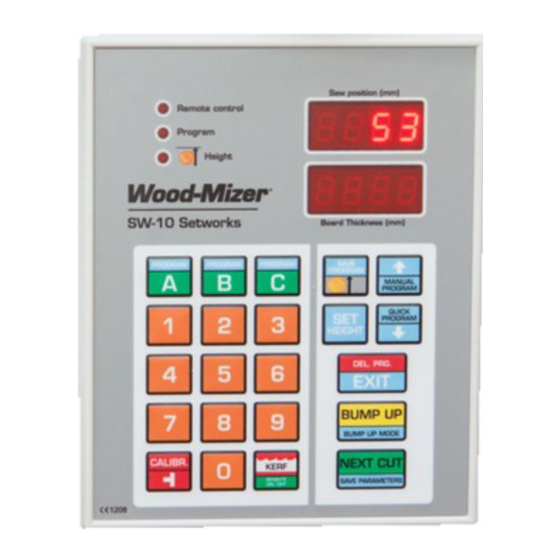
OPERATION SW-10 Controller Panel SECTION 2 OPERATION WARNING! In DC sawmills (with a gas or diesel engine), the Setworks must not be operated when the main engine is turned off. SW-10 Controller Panel See Figure 2-1. Remote mode Current blade activated height Controller works... - Page 18 OPERATION SW-10 Controller Panel Descriptions of the controller panel buttons: A, B, C - Board thickness memory buttons, program memory buttons SAVE PROG - confirming a program, setting a head return height MANUAL PROGRAM - activating the Manual Program mode, switching items upwards QUICK PROGRAM - activating the Quick Program mode, switching items downwards SET HEIGHT - entering a real distance between the blade and the sawmill bed DEL.
-
Page 19: Start-Up Settings Of The Controller
Enter the kerf value. NOTE: We recommend using Wood-Mizer blades only. For the Wood-Mizer blades, the kerf value should be 2mm, so you should press “2” and “0” buttons. Kerf values with an accuracy of up to 0.1 mm can be entered into the memory of SW-10 Setworks. - Page 20 OPERATION Start-up Settings of the Controller See Figure 2-2. FIGURE 2-2 To save the kerf value setting, press . The controller will display the text “SAVE” and will exit the function. NOTE: From this moment, the Setworks controller will be calculating next cutting positions taking into account the stored kerf value.
- Page 21 OPERATION Start-up Settings of the Controller Switch on the controller and wait until the text ’’SW-10” disappears. Set the head with the blade at the height of 150 mm. Press and hold down . The text ’’Auto CALL” will appear on the display. The controller is now ...
- Page 22 OPERATION Start-up Settings of the Controller If the blade height on the display is incorrect, press and hold down . The upper display will show horizontal dashes. Enter the correct blade height dimension (using the keypad) and press The end of the function will be signaled and the normal mode of operation will be restored. ...
-
Page 23: Operation In Normal Mode
OPERATION Operation in Normal Mode - To save the parameter, push Operation in Normal Mode CAUTION! The minimum thickness of the last board (when using the automatic modes) cannot be lower than 30 mm [LT15, LT20 and WM1000 sawmills] or 50mm [LT40 sawmills]. To cut a thinner board, you need to manually lower the saw head. -
Page 24: Controller Operation In Pre-Defined Head Return Height Mode
OPERATION Controller Operation in Pre-defined Head Return Height Mode position. Only the first cut position has to be set manually. NOTE: After making the first cut you will not need to set the head height manually. Controller Operation in Pre-defined Head Return Height Mode If you want to saw without removing each cut board, you should preprogram the head return height. - Page 25 OPERATION Controller Operation in Pre-defined Head Return Height Mode Select the board thickness and press When the cut is made, press ; the head will go up to the preprogrammed height above the log or cant. Press and the saw head will drop by the selected board thickness to the next cut ...
-
Page 26: Remote Mode
OPERATION Remote Mode Remote Mode The SW-10 controller is adapted for use along with the sawmill up/down switch. Therefore, during cutting you can use the up/down switch instead of the buttons. The Remote mode is activated with the button. After activating of this function, the “Remote control” light should come on. The Remote mode is activated automatically after confirming a sawing program. -
Page 27: Pattern Modes
OPERATION Pattern Modes Pattern Modes To create a series of cuts calculated from the bed level, use one of the Pattern modes: Manual Program or Quick Program. These two modes can be used for entering a program for cutting one log only. Such programs are not saved in the controller memory and are deleted when the cutting operation is completed. -
Page 28: Quick Program" Mode
OPERATION Pattern Modes Start the cutting process. When cutting, use the buttons, as in the normal mode. 2.7.1 ’’Quick Program” Mode The Quick Program mode can be used to quickly create a program of cuts referenced from the sawmill bed. In this mode, it is not necessary to enter each board thickness value, as opposed to the Manual Program mode. -
Page 29: Storing Programs In The Setworks Memory
OPERATION Pattern Modes 2.8.1 Storing Programs in the Setworks Memory The controller allows the operator to create and store three sawing programs. Thus, the operator can quickly activate a program with frequently used board dimensions, saving time needed for making changes in any existing program. - Page 30 OPERATION Pattern Modes Finish activating of the program by pressing . If the head return height was preset, the ’’Height” light will come on indicating that this value was saved. CAUTION! Remember to set the head at the first cut height before you finish activating of the program.
- Page 31 OPERATION Pattern Modes Remove the boards. Cut 1 25mm Cut 2 28mm Cut 3 50mm Cut 4 100mm 100mm FIGURE 2-2 OPERATION SW-10doc111419 2-15...
-
Page 32: Troubleshooting
Troubleshooting Setworks Malfunction SECTION 3 TROUBLESHOOTING Setworks Malfunction PROBLEM CAUSE SOLUTION Setworks does not work. Magnet sensor improperly Align the magnet sensor as shown adjusted in figures 3-1 and 3-2. Calibrate the When performing a program, controller. See Section the controller disengages the Auto-calibration. - Page 33 Troubleshooting Setworks Malfunction Setworks stops the saw head Blade height sensor signal is - Check the connections between and ’’Err PULS” appears on bad. the blade height sensor and the the display. controller. - Check if the encoder or the magnetic strip (depending on the machine) is not loose.
- Page 34 Troubleshooting Setworks Malfunction Sensor Alignment Bolts (4) FIG. 3-1 SW-10doc111419 Troubleshooting...
- Page 35 Troubleshooting Setworks Malfunction Sensor Magnetic Strip .1-2 mm Distance from the magnet sensor to the magnetic strip 1 deg. 3 deg. Maximum sensor’s deviation from the vertical axis 3 deg. Maximum sensor’s deviation from the horizontal axis FIG. 3-2 Troubleshooting SW-10doc111419...
-
Page 36: Replacement Parts
Poland at +48-63-2610233. From the continental U.S., call our toll-free Parts hotline at 1-800-448-7881. Have your customer number, vehicle identification number, and part numbers ready when you call. From other international locations, contact the Wood-Mizer distributor in your area for parts. -
Page 37: Mounting Kit, Sw-10 For Lt15
Mounting Kit, SW-10 for LT15 REF. DESCRIPTION (* INDICATES PARTS AVAILABLE IN ASSEMBLIES ONLY) PART # SETWORKS MOUNTED ON THE MILL, LT15 AC/DC 500624 COVER, LT15 SW-08 SETWORKS 099318 SW-10 SETWORKS CONTROLLER 500628 HOUSING, SW-08 SETWORKS REAR 100877 ENCODER, 50IMP./R. 096016 COUPLING, ENCODER 520983... -
Page 38: Setworks For Lt15P And Lx100
REPLACEMENT PARTS SW-10 Setworks for LT15P and LX100 SW-10 Setworks for LT15P and LX100 REF. DESCRIPTION (* INDICATES PARTS AVAILABLE IN ASSEMBLIES ONLY) PART # SW10 SETWORKS FOR LT15P & LX100 515300 MAGNETIC STRIP W/MOUNTING BRACKET 516133 BRACKET, MAGNETIC STRIP MOUNT 516131-1 WASHER, 4.3 FLAT ZINC... - Page 39 REPLACEMENT PARTS SW-10 Setworks for LT15P and LX100 REF. DESCRIPTION (* INDICATES PARTS AVAILABLE IN ASSEMBLIES ONLY) PART # NUT, M6-8-B HEX NYLON ZINC LOCK F81031-2 BOLT, M6X20 8.8 HEX HEAD FULL THREAD ZINC F81001-2 WASHER, 8.4 FLAT ZINC F81054-1...
Need help?
Do you have a question about the SW-10 SETWORKS and is the answer not in the manual?
Questions and answers
What will be the symptoms if sw10 is coming on and off?
The context does not provide specific symptoms of the Wood-Mizer SW-10 Setworks turning on and off. However, it mentions that after switching on, the "SW-10" inscription appears on the display, and the Setworks is ready for operation within a few seconds. If the encoder impulse direction is incorrect, the saw head height on the display may rise during downward movement, indicating a wiring issue. This incorrect behavior may cause the controller to not work correctly.
This answer is automatically generated