
Related Manuals for QRP Labs 10W HF Linear PA


Summary of Contents for QRP Labs 10W HF Linear PA
- Page 1 10W HF Linear PA 10W HF Linear Power Amplifier kit assembly manual A low-cost, high-performance HF Linear PA covering 2-30MHz Designed and produced by QRP Labs, 2018 10W HF Linear PA kit assembly 1.00...
-
Page 2: Table Of Contents
Install voltage regulator IC201 ........................27 3.30 Install transistors Q207 and Q208 ........................28 3.31 Install heatsink ..............................30 Applications information ............................32 PA Precautions ..............................32 Connections ..............................32 Adjustment ..............................32 Tests undertaken ............................33 10W HF Linear PA kit assembly 1.00... -
Page 3: Introduction
In the event of a mistake, it is always best to detect and correct any errors as early as 10W HF Linear PA kit assembly 1.00... -
Page 4: Assembly
This parts list shows the through-hole components to be inventoried and installed in the assembly. Resistors R201, 216, 217 220-ohm ¼W, red-red-black-black-brown (3pcs) R203, 204, 209, 210 220-ohm ½W, red-red-black-black-brown (4pcs) R202 22K, red-red-black-red-brown 10W HF Linear PA kit assembly 1.00... - Page 5 Washer Large washer Insulating washer 2pcs white plastic insulating washer 9mm M3 bolt 9mm M3 bolt 15mm M3 bolt 15mm M3 bolt Rubber tube Short ~4mm length of rubber tube Heatsink Custom-manufactured 130x28x25mm 10W HF Linear PA kit assembly 1.00...
- Page 6 10W HF Linear PA kit assembly 1.00...
-
Page 7: Trace Diagram And Parts Layout
Practically everything on both layers that isn’t a RED or BLUE track, is ground-plane! The two ground-planes are connected at frequent intervals (not more than 0.1-inches) by vias. 10W HF Linear PA kit assembly 1.00... - Page 8 10W HF Linear PA kit assembly 1.00...
-
Page 9: Schematic
3.3 Schematic 10W HF Linear PA kit assembly 1.00... -
Page 10: Wind And Install Inductor L201
Install it on the PCB, cut the wires to 2mm and as usual, solder it for at least 10 seconds to ensure the enamel burns off. Test for DC continuity between the 12V pad of the PCB (indicated in the black circle) and the positive pad of capacitor C204 (indicated in the red circle). 10W HF Linear PA kit assembly 1.00... -
Page 11: Wind And Install Transformer T201
Now it is necessary to identify the wires of the bifilar winding. So, tin the ends (by scraping enamel off, or holding the wire ends in a blob of molten solder for 10 seconds). Use a DVM 10W HF Linear PA kit assembly 1.00... - Page 12 “B”, and DC continuity across the pads of R204, which is winding “A”. If either of these tests reveals no DC continuity, then go back and check the soldering of the appropriate T201 transformer winding. 10W HF Linear PA kit assembly 1.00...
-
Page 13: Wind And Install Transformer T202
10 seconds or more until the enamel has burned off and a good joint is made. With these thin wires the burning method is quite easy. Now undertake the usual continuity test. 10W HF Linear PA kit assembly 1.00... -
Page 14: Wind And Install Transformer T203
So, I find it helpful to scrape the wire ends a little using a wire-cutter, THEN tin them with solder for 10 seconds. 10W HF Linear PA kit assembly 1.00... - Page 15 4 holes – you will have had to correctly identify the wires as described. If there is no DC continuity then go back and check the soldering of the 4 wires (and check that the enamel was properly scraped/burnt off). 10W HF Linear PA kit assembly 1.00...
-
Page 16: Install Capacitor C213
The amplifier won’t work well if the 2-turn and 3-turn windings are mixed up. Insert the two right-hand winding ends (2-turns) in the corresponding two holes in the PCB which are on either side of capacitor C213. 10W HF Linear PA kit assembly 1.00... - Page 17 There is no way to check the continuity of the 2-turn “input” winding of T204 because there is already DC continuity through the windings of T203. So careful soldering and an inspection with a jeweller’s loupe or magnifying glass are the only options available. 10W HF Linear PA kit assembly 1.00...
-
Page 18: Install Capacitors C211 And C212
3.10 Install capacitors C211 and C212 These two capacitors are 1uF ceramic capacitors with label “105”. 3.11 Install remaining ceramic capacitors The remaining 10 ceramic capacitors are all 0.1uF ceramic capacitors with label “104”. 10W HF Linear PA kit assembly 1.00... -
Page 19: Install Inductors L202, L203, L204 And L205
3.13 Install resistors R203, R204, R209, R210 These are 220-ohm 0.5W resistors. They have colour code red-red-black-black-brown, but you can also easily identify them because they are larger than the other resistors. 10W HF Linear PA kit assembly 1.00... -
Page 20: Install Resistors R201, R216 And R217
These are 220-ohm resistors with colour code red-red-black-black-brown. Be careful with the identification of resistors on this PA PCB because lots of them start with colour code red-red. 3.15 Install resistors R207 and R208 These are 2.2-ohm resistors with colour code red-red-black-silver-brown. 10W HF Linear PA kit assembly 1.00... -
Page 21: Install Resistors R213 And R218
3.16 Install resistors R213 and R218 These are 10K resistors with colour code brown-black-black-red-brown. 3.17 Install resistors R212 and R214 These are 47-ohm resistors with colour code yellow-purple-black-gold-brown. 10W HF Linear PA kit assembly 1.00... -
Page 22: Install Resistor R202
3.18 Install resistor R202 R202 is a 22K resistor colour-coded red-red-black-red-brown. 3.19 Install resistor R205 R205 is a 2.2K resistor with colour code red-red-black-brown-brown. 10W HF Linear PA kit assembly 1.00... -
Page 23: Install Resistor R206
R206 is a 33-ohm resistor with colour code orange-orange-black-gold-brown. 3.21 Install trimmer resistors R211 and R215 These are trimmer resistors, with code “472” Rotate the trimmer potentiometers all the way anticlockwise at this time! 10W HF Linear PA kit assembly 1.00... -
Page 24: Install Capacitor C204
C204 is a polarized 470uF electrolytic capacitor. As previously, ensure that the capacitor is orientated correctly as per the PCB silkscreen. The long wire is positive and must be inserted in the hole marked +. 10W HF Linear PA kit assembly 1.00... -
Page 25: Install Diode D201
Bend the middle leg slightly away from the flat face so that it fits the triangular holes on the PCB. Ensure the transistor flat is orientated the same way as the silkscreen flat. 10W HF Linear PA kit assembly 1.00... -
Page 26: Install Transistors Q202, Q203 And Q204
PCB silkscreen. Inspect the joints with a jeweller’s loupe or magnifying glass to be sure the connections have been made. 10W HF Linear PA kit assembly 1.00... -
Page 27: Install Transistor Q205
Bend the central wire slightly away from the flat face and install it with the flat on the IC matching the flat drawn on the PCB silkscreen. The correct orientation is vital. 10W HF Linear PA kit assembly 1.00... -
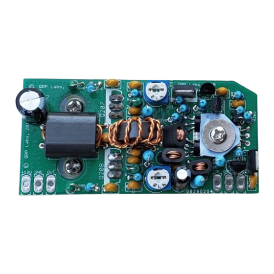
Page 28: Install Transistors Q207 And Q208
Note that the M6 nut at the left is part of the assembly to the heatsink and has not been done yet in these assembly instructions. See next page for a photograph of the PCB bottom view. Check it before soldering Q207/8. 10W HF Linear PA kit assembly 1.00... - Page 29 The top view of the completed PA board looks like this. (Note, here the board is shown mounted on the heatsink, by three nuts, one on each of the IRF510s and one on the BS170 driver assembly). 10W HF Linear PA kit assembly 1.00...
-
Page 30: Install Heatsink
Thread this onto the 15mm bolt that was passed through the PCB, in step 3. This nut will act as a spacer between the PA PCB and the actual heatsink. It is also a heat conduit from the PCB to the heatsink. 10W HF Linear PA kit assembly 1.00... - Page 31 PCB. The leftmost two wires are +12V and GND respectively. You can touch the probes to these connection points, with the board assembly upside-down. 11) When powering up the radio, it is best to use a current-limited supply, set to 300mA, as a final precaution. 10W HF Linear PA kit assembly 1.00...
-
Page 32: Applications Information
Apply power, while observing the current consumption. You can do this with a power supply with current metering, or using a DVM in series with the power supply. Connect the /TX input to ground, to switch on the amplifier. Do not apply any input RF at this stage. 10W HF Linear PA kit assembly 1.00... -
Page 33: Tests Undertaken
In all of the tests, there were no failures of components and no degradation of performance. 1) Gain: 26 to 28dB, with +/- 1dB gain flatness over the range 2-30MHz. This is shown in the following images. 10W HF Linear PA kit assembly 1.00... - Page 34 8) A clean 3.5MHz (80m band) source running at 10W output had 2 harmonic at -38dBc and harmonic at -31dBc – very good linearity 9) Operated at full-power continuous key-down, 100% duty-cycle for 1 hour, without damage or degradation in performance. 10W HF Linear PA kit assembly 1.00...
Need help?
Do you have a question about the 10W HF Linear PA and is the answer not in the manual?
Questions and answers