Table of Contents
Advertisement
Quick Links
Advertisement
Table of Contents

Related Manuals for TrackWeight I Series

Summary of Contents for TrackWeight I Series
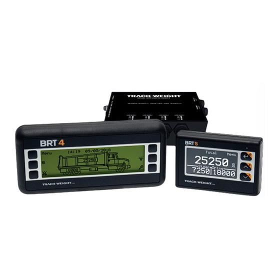
- Page 1 INSTALLATION MANUAL SCALES FOR TRUCKS BRT4 BRT5 & SERIES I V1.0.0...
-
Page 3: Table Of Contents
Table of Contents TABLE OF CONTENTS ..........................3 INTRODUCTION ............................4 MAIN CONFIGURATIONS .......................... 5 ..............................5 TRAILER 6 – 10- ............................ 6 WHEEL TRUCK ............................7 WHEEL TRUCK INSTALLATION OF THE MONITOR AND COMMUNICATION BOX ..............8 ..............................8 OMPONENTS .............................. -
Page 4: Introduction
To do this, your authorized reseller will be able to adjust your TrackWeight scale according to your needs. If you do the installation yourself, no problem. Consult this installation manual to guide you step by step. Then flip through your user manual as it contains all the information you need to set up, calibrate and use your scale. -
Page 5: Main Configurations
Main configurations Semi-trailer Installation Manual | V1.0.0 | 5... -
Page 6: 6 - 10-Wheel Truck
6 – 10-wheel truck Installation Manual | V1.0.0 | 6... -
Page 7: 12-Wheel Truck
12-wheel truck * If it is a lift axle, it is possible to replace the mechanical sensor with an air sensor depending on the type of suspension. Installation Manual | V1.0.0 | 7... -
Page 8: Installation Of The Monitor And Communication Box
Installation of the monitor and communication Components Quantity Part Number Component BRT 6299 (or BRT 6298) BRT 5 Monitor (or BRT 4) BRT 5300 Communication Box BRT 5137 Power cable BRT 5 monitor cable (or BRT 4 BRT 5136 (or BRT 5138) Monitor cable) Installation Manual | V1.0.0 | 8... -
Page 9: Installation
Installation 1. Identify a location with enough space to accommodate the BRT 4/5 monitor. Note: It is possible to install the monitor in the dashboard or on the top of the dashboard with the stand. 2. The communication box is located inside the dashboard. You must select a location to protect it with enough space to allow the installation of sensors and cabling. - Page 10 4. The communication box operates on a current of 12-24 VDC. Connect the power cable (BRT 5137) to the fuse board. The red wire must be connected to a stable source with a free fuse (minimum 5A). The black wire must be added to the board's common neutral (or other neutral) for the scale monitor only.
-
Page 11: Installation Of Air Sensor On Trailer Or 6 - 10 - 12-Wheel Trucks
Installation of air sensor on trailer or 6 - 10 - 12- wheel trucks Components If one height valve: Quantity Part Number Component BRT 560 Air Sensor REQUIRED TOOLS BRT 5053 (or BRT ¼’’ T-tube fitting (or ⅜’’ 5055) x ⅜’’ x ¼’’ tube) - Monkey wrench BRT 5220 ¼’’... -
Page 12: Additional Components (Tractor-Trailer)
Additional components (tractor-trailer) In addition to the components listed above, you should have at least one of these components for installing an air sensor on tractor-trailer configurations. Quantity Part Number Component BRT 580 Twisted air hose with service hand BRT 582 ⅜... -
Page 13: Installation On Tractor-Trailer Configuration
BRT 587 (straight, quick plug). 1. Identify the number of height valves on the tractor. 2. For each system controlled by a valve, an air line must lead to the TrackWeight communication box. 3. Cut the air line as close as possible to the balloon to insert a BRT 5053 or BRT 5055 "T"... - Page 14 8. Insert the assembly made in Step 6 into the hole from the outside and from the side of the BRT 5076 (the part on the side of the BRT 5047 part on the front side of the truck). 9. Secure everything from the inside with the washer and nut from the BRT 5076 component.
-
Page 15: Trailer End
Trailer end 14. Identify the number of height valves on the trailer. 15. For each system controlled by a valve, an air line must lead to the TrackWeight communication box. 16. Cut the air line as close as possible to the balloon to insert a BRT 5053 or BRT 5055 "T"... -
Page 16: Wheel Truck Configuration
Installation on 6 - 10 - 12-wheel truck configuration 1. Identify the number of height valves on the truck. 2. For each system controlled by a valve, an air line must lead to the TrackWeight communication box. 3. Cut the air line as close as possible to the balloon to insert a BRT 5053 or BRT 5055 "T"... -
Page 17: Installing A Mechanical Rt Sensor
Installing a mechanical RT sensor Components REQUIRED TOOLS - Two metal clamps (between 12'' and 18'') - Small mass - ⅜ ratchet wrench with 9/16 short and 7/16 long sockets - Rod or welding rod 7018 - Measuring tape - Marking pen for use on metal - Angle grinder with grinding disc (¼) - Pre-cut, adjustable, metal... -
Page 18: Installation
Installation 1. Determine the correct location for sensor installation. Note: Make sure that the RT sensor does not interfere with fixed or moving parts of the vehicle. › For the front axle(s): Ideally in the center of the axle. However, be sure to check the clearance of the truck and have a good clearance (with the protective cover) so that the sensor does not catch on the oil pan or any other part of the truck. - Page 19 3. Place the fixed and adjustment block at the center of the width of the chosen location on the structure (axis or "beam"). The blocks should be placed face-to-face within 50 ± 2 mm of each other. Section to be measured Centre of the section to be measured Centre...
- Page 20 7. Make a weld in 3 passes on each side of the two blocks. The weld must exceed the blocks by at least 15 mm. Example 8. Vertically weld 2 ¼-20 x ½" steel bolts (or rustproofing, depending on option purchased) at the position shown in the image below.
- Page 21 ("L" shape). Force the two ¼-20 x ½" bolts through the foam. 11. Insert the threaded portion of the TrackWeight load cell (sensor) into the hole in the adjustment block ("L" shape).
- Page 22 14. Connect the RT sensor to the communication box on one of the inputs and note its position. 15. From the TrackWeight scale monitor, navigate to the "Diagnosis" menu for BRT 5. For BRT 4, navigate to the "Advanced Diagnosis 2" menu.
- Page 23 18. Using a hammer, lightly strike just one side (or both) of the stationary block (see image below) while continuously reading the signal on the scale monitor (or the multimeter). If the signal decreases, tighten the vertical locking nut to -40.0 mV and strike lightly again.
- Page 24 22. Secure the protective cover with the two ¼-20 flanged nuts. 23. Use tie wraps to hold the cable in place all the way to the communication box. Installation Manual | V1.0.0 | 24...
-
Page 25: Appendix 1 - Matching Of Rt Sensor Signals
GND (-) Signal (-) Signal (+) The TrackWeight scale adjusts the ALIM voltage to +10.0 VDC relative to the GND, which matches the recommended value. The adjustment and operating voltage is read between the green and white wires. Installation Manual | V1.0.0 | 25... -
Page 26: Appendix 2 - Rustproof Weld Procedures
Appendix 2 - Rustproof Weld Procedures Installation Manual | V1.0.0 | 26... -
Page 27: Installation Of Optional Accessories
Installation of optional accessories Exterior lights/ alarms (BRT 620-M, BRT 622) Note: The illustration shows the lights installed directly on the truck chassis. However, a bracket is also available. Connection diagram for the set of 2 lights (BRT 620-M): Connection diagram for the set of 3 lights (BRT 622): The gnd is shared in the communication box Installation Manual | V1.0.0 | 27... -
Page 28: Imprimante (Brt 504)
Imprimante (BRT 504) 1. Disconnect the power wire (red and black) from the communication box. 2. Connect the wire supplied with the printer to the "Power - 12/24 VDC" port (red and black) of the communication box and the other end to the power wire. 3. -
Page 29: Contact Us
Business hours Monday to Friday 8:00 am to 5:00 pm (Eastern time) The TrackWeight product line; RT, BRT 4 and BRT 5 sensors are the property of TrackWeight Systems Inc. All rights reserved 2018. V1.0.0 Installation Manual | V1.0.0 | 29... -
Page 30: Update Notes
Update Notes V1.0.0 (BRT06340.1 Installation Manual FR TrackWeight S1) Creation of the TrackWeight BRT4 and BRT5 installation Manual Installation Manual | V1.0.0 | 30... - Page 31 .COM Manufacturer of on-board scales for trucks and semi-trailers Exclusive Dsitributor in Quebec RMTEQUIP.COM 30, Emilien-Marcoux, suite 101 Blainville, QC, Canada J7C 0B5 Sales, parts and service: 1 877 663-4311...
Need help?
Do you have a question about the I Series and is the answer not in the manual?
Questions and answers