Table of Contents
Advertisement
Advertisement
Table of Contents

Related Manuals for Ultra Optics Rx


Summary of Contents for Ultra Optics Rx
- Page 1 www.ultraoptics.com...
-
Page 2: Thank You
Introduction This manual is intended for use by Ultra Optics customers. It is important to read and understand the information in this manual before installing or operating the system. This manual is provided by Ultra Optics to its customers as a courtesy and, except as expressly provided in this manual, ULTRA OPTICS MAKES NO WARRANTIES, EXPRESS OR IMPLIED, REGARDING THE CONTENTS IN THIS MANUAL. -
Page 3: Design Modification
Additional Copies Additional copies of this manual are available by contacting Ultra Optics by phone at 763.488.6030, or by visiting our website at www.ultraoptics.com. No part of this document may be reproduced or copied in any form, or by any means, without the prior written permission of Ultra Optics. -
Page 4: Safety
Safety SAFETY FIRST! The Rx is a complex piece of equipment that contains various safety hazards. Some of these hazards include, but are not limited to: Do not service machine while it is plugged in. Service work should only be conducted by properly trained technicians. - Page 5 The machine should be checked for any visible damage during each shift. Any changes, including changes in operation behavior, must be reported to the supervisor. The Rx is intended to run with an operator present at all times. It is not intended to be operated unattended. www.ultraoptics.com...
-
Page 6: Table Of Contents
Table of Contents Introduction ..........................i Thank You ..........................i Symbols ........................... i Service ............................. i Design Modification ......................... ii Additional Copies ........................ii Safety ............................iii Required Utilities ........................1 Machine connections ......................1 System Overview ........................2 General Overview ........................2 Lens Load/Unload ........................ - Page 7 Maintenance Procedures .......................17 Setting spindle speeds .......................17 Adjusting the curing lamp time ...................18 Removing the curing lamp ....................18 Adjusting the coating height ....................19 Priming the wash pump ......................19 Ensuring the lens is dry before coating ................19 Replacing the coating filter ....................20 Lens retrieval from UV light module ...................20 Flushing coating .........................21 Changing Filters .........................22...
-
Page 8: Required Utilities
Machine connections The Rx requires two cords to be plugged into the back of the machine. One cord is the power cord that connects the 115 VAC power supply to the back of the machine. With reference to Figure 1, the connector on the right is round and is used to connect the supplied foot switch. -
Page 9: System Overview
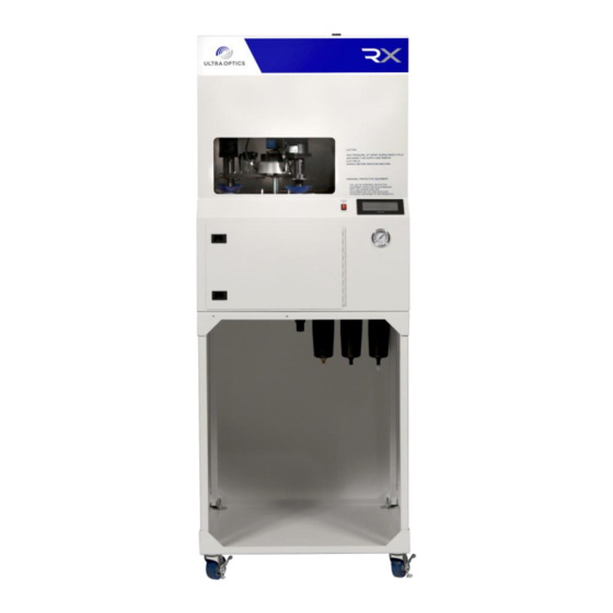
System Overview General Overview The Rx is a robust backside hard coating machine that performs all of the required operations within a single machine. The core coating functions utilize the same technology as the highly- touted MR3 coating system. These key processes are arranged and packaged in a way to reduce cost for today’s small to medium sized labs. -
Page 10: Wash Process
Wash process The lens is washed with high pressure, deionized water. The clean deionized water is stored in a reservoir in the bottom of the machine. When a wash cycle starts, clean water is drawn through a filter (located inside the reservoir) and out of the reservoir, into the pneumatically driven pump. -
Page 11: Cure Process
Figure 5 - Coating system schematic Cure process The Rx is designed to cure Ultra Optics’ line of UV-based coatings. After the lens has completed the coating application cycle, the lift cylinder will raise the arm assembly, which will then rotate and drop down into the curing station. An ultra-violet lamp resides in the curing station. -
Page 12: System Operation
System Operation Start-up Procedure The following procedure should be followed upon machine start-up. 1. Inspect the machine to be sure nothing is in it that would impede the movement of the spindle assembly 2. Turn air supply on 3. Fill clean/wash water reservoir with deionized water and empty the waste water reservoir 4. -
Page 13: Main Screen
Main Screen MACHINE SET UP SINGLE LENS CYCLE SYSTEM DETAILS TWO LENS DIAGNOSTICS CYCLE – Selecting this button will bring up the SINGLE LENS screen. Only one SINGLE LENS CYCLE spindle will be utilized during this cycle. – Selecting this button will bring up the TWO LENS screen. Two spindles TWO LENS CYCLE will be utilized during this cycle. -
Page 14: Single Lens Cycle Screen
Single Lens Cycle Screen SINGLE LENS MENU CYCLE STOP VAC1 CYCLE LENS DIAGNOSTICS ALARM Use the following procedure to begin the single lens cycle: 1. Select ON/OFF button to put it in the ON position a. At this time, the vacuum will turn 2. -
Page 15: Two Lens Cycle Screen
Two Lens Cycle Screen TWO LENS MENU CYCLE STOP VAC1 VAC2 CYCLE LENS DIAGNOSTICS ALARM Use the following procedure to begin the two lens cycle: 1. Select ON/OFF button to put it in the ON position a. At this time, the vacuum will turn on 2. -
Page 16: Machine Set-Up Screen
REMOVE LAMP TIMER IN SECONDS VALVE This screen is used for individual activation of major functions of the Rx. – Selecting this button will return to the Main Screen. MENU – Selecting this button will turn the coating pump on/off. - Page 17 Important Note: If button reads “INDEX NOT HOME”, the spindles will rotate to the home index position by selecting the HOME INDEX button. – Selecting this button will return the spindles to the home position HOME INDEX – Selecting this button will bring up the Lamp Removal Screen REMOVE LAMP –...
-
Page 18: System Detail Screen
System Detail Screen SPINDL SPINDL MENU HOME DONE E1 ON E2 ON COAT COAT SPINDL HOME SPINDL INDEX INDEX WASH WASH COAT RESET LENS SPIN COUNTE This screen is used to measure individual spindle speeds. Each spindle is numbered. Locate spindles #1 or #2 by selecting the INDEX button. -
Page 19: Lamp Removal Screen
Lamp Removal Screen UV Lamp MENU LAMP LAMP REMOVE HOMED – Selecting this button will return to the Main Screen. MENU – Selecting this button will put the lamp in position for removal. LAMP REMOVE – Selecting this button will put the lamp back in the home position. LAMP HOME –... -
Page 20: Diagnostics Screen
Diagnostics Screen MENU VACUUM POSITION HMI Rev. X.XX ALARM HISTORY PLC Rev. X.XX – Selecting this button will return to the Main Screen. MENU – Selecting this button will bring up the Vacuum Test Screen. VACUUM – Selecting this button will bring up the Position Test Screen. POSITION –... -
Page 21: Vacuum Test Screen
Vacuum Test Screen MENU HOME DONE VAC 1 VAC 2 HOME INDEX INDEX VACUUM VACUUM – Selecting this button will return to the Main Screen. MENU – Selecting these buttons will activate the vacuum. A lens can be VACUUM 1/VACUUM 2 placed on each spindle for testing vacuum. -
Page 22: Position Test Page
Position Test Page MENU CYL UP LAMP HOME LAMP EXT VAC 1 VAC 2 CYL DWN MAINT. DOOR LAMP DOOR INDEX HOME INDEX POS FOOT PDL LIGHT CRT This is a visual reference screen to monitor the machine’s positions and inputs on the PLC. –... -
Page 23: Maintenance
Maintenance The Rx system is designed to provide many years of reliable and efficient processing of ophthalmic lenses. Its ability to provide this service is significantly enhanced with proper maintenance. Due to the many integrated systems within the Rx, it is highly recommended that service and maintenance is only done by trained technicians. -
Page 24: Maintenance Procedures
Coating spin-off speed: 2000 RPM, 1600 RPM if using AST-1 coating The following procedures should be followed to check the spindle speeds using a non-contact measurement device. This tachometer can be rented or purchased from Ultra Optics as part number 1397. Preparation: 1. -
Page 25: Adjusting The Curing Lamp Time
Figure 7. a. This reflective tape is supplied with the tachometer if acquired from Ultra Optics. Setting Wash Speed 1. From the main control screen, select SYSTEM DETAILS 2. Select SPINDLE 1 ON COAT 3. -
Page 26: Adjusting The Coating Height
2. Select ON/OFF 3. Prepare a lens and place it on the suction cup of the wash spindle 4. Allow the Rx to wash and dry the lens 5. When the spindle arm assembly starts to come up, select CYCLE STOP 6. -
Page 27: Replacing The Coating Filter
Replacing the coating filter 1. Open the front service panel 2. Disconnect the nut on the elbow on the bottom of the reservoir, see top red circle in Figure 10 3. Insert loose nut and tubing into a clean container 4. -
Page 28: Flushing Coating
If reflectors are not clean and cannot be cleaned, contact Ultra Optics and replace module with a new one. 13. Plug module back into carriage 14. Secure with two screws removed in step #8 15. Close back service door 16. -
Page 29: Changing Filters
remove air. Allow pump to run for five to ten minutes to release any air from the system. b. If the filter is free of air, run a few sample lenses to ensure there are no streaks or defects. OPTIONAL: WARNING! Allow the machine to cool for 30 - 60 minutes before flushing with acetone! -
Page 30: Spindle Suction Cups
3. Select LAMP REMOVE 4. Turn machine power off at the red switch on the front panel 5. Disconnect power cord from the back of the machine 6. Open the back service door of the machine 7. Remove the two pan head phillips screws that hold the UV light module in place 8. -
Page 31: Replacing The Spindle Motor Assembly
Replacing the Spindle Motor Assembly 1. Remove the suction cup. 2. Disconnect the spindle motor power cable from the back of the spindle. 3. Disconnect the vacuum tubing from back of the spindle. 4. Loosen the bolt on the front tip of the spindle swing arm. 5. -
Page 32: Electrical Panel Layout Information
Control relays Wash speed drive board Pump drive board Coat speed drive board Lamp speed drive board Valve manifold Mercury Vacuum switch sensor Vacuum generator Solid state Figure 13 - Picture of Rx control panel relay www.ultraoptics.com page 25... - Page 33 PANASONIC PANASONIC FP-X C30R FP-X E16R PLC OUTPUTS PLC INPUTS Y0: Lamp high mercury switch X1: Vacuum spindle 1 Y1: Vacuum spindle 1 X2: Vacuum spindle 2 Y2: Vacuum spindle 2 X3: Cylinder up Y3: Cylinder up X4: Cylinder down Y4: Cylinder down X5: Light curtain Y5: Wash pump...
- Page 34 Figure 14 - Circuit breaker layout CIRCUIT BREAKER LAYOUT Machine breaker 5 AMP Index motor Lamp breaker 5 AMP 24vdc power supply 5 AMP PLC breaker 3 AMP Speed board 1 3 AMP Speed board 2 3 AMP Speed board 3/Lamp motor 5 AMP HEPA outlet breaker 3 AMP Lamp fans Wash motor...
- Page 35 Figure 15 - Circuit breaker wiring Figure 16 - Control relay layout www.ultraoptics.com page 28...
-
Page 36: Common Replacement Parts
Common Replacement Parts The following table identifies the commonly replaced parts on the Rx machine: Part Number Description Unit Picture 3404 UOC coating filter Each 4404 UOC 5 micron water filter Each 1428 Air dryer filter pack Each Suction cup – clear cleated... -
Page 37: Coating Troubleshooting Solutions
The following figures are provided as a starting point to help troubleshoot any coating issues. Wagon wheel effect- The coating height needs to be adjusted. The coating flow should stream to the top of the bowl. 1 – 2 single streaks across the lens this would be caused from air in the coating filter. - Page 38 Large pits with runs behind streak: if you can feel the pit with your finger it is most likely debris on the lens. Check your cleaning procedures, ensure wash tip is free and clear of debris and wash pump is working properly. It there is a glob of coating left on the center of the lens;...
-
Page 39: Alarm Codes
ABORT CYCLE ALARMS **These alarms indicate a serious event and abort the lens cycle ** Alarm Message Cause Lost Vacuum Alarm A lens has fallen from the suction cup Arm Not Down The Cylinder Down sensor is not ON three seconds after the Cylinder Down solenoid was activated Arm Not Up The Cylinder Up sensor is not ON three seconds after... -
Page 40: Spare/Replacement Parts
The following spare parts can be ordered by calling our Customer Service team at 763.488.6030, or by going online at www.ultraoptics.com. Part Number Item Unit of Measure 01127 UV-87 coating 1 bottle 01084 UV-NV coating 1 bottle 01158 AST-1 coating 1 bottle 01041 Isopropyl Alcohol (IPA) -
Page 41: Warranty Statement
Warranty The Corporation warrants the new equipment of its manufacturer to be free from defective material or workmanship for a period of (12) twelve months from date of shipment from the factory when given normal and proper usage and while owned by the original Purchaser from the Corporation. -
Page 42: Product Liability
Product Liability The Corporation believes that the equipment conforms to the requirements of the Occupational Safety and Health Act of 1970 but, because Interpretations of such requirements may vary no representation or warranty is made with respect to such compliance. All Safety devices and guards included in the proposal are recommended for purchase.
Need help?
Do you have a question about the Rx and is the answer not in the manual?
Questions and answers