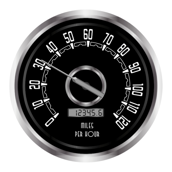
Summary of Contents for NVU New Vintage 1940
- Page 1 NEW VINTAGE INSTRUMENT AND GAUGE KIT INSTALLATION INSTRUCTIONS AIR CORE GAUGES WOODWARD, 1967, 1940, PERFORMANCE REV120414...
- Page 2 INDEX THE BASICS, TOOLS AND SENDERS page 2 SPEEDOMETER QUICK SET-UP page 3 INSTALLATION DIAGRAMS page 4-7 PROGRAMMABLE SPEEDOMETER SUPPLEMENTAL page 8-13 TROUBLESHOOTING page 14 Thank you for choosing New Vintage USA products. We strive to provide the finest quality and design components available on the market. If you need technical assistance, please call 248.850.5482 or email info@newvintageusa.com New Vintage USA 5-Year Warranty New Vintage USA warrants all merchandise against defects in workmanship and...
- Page 3 Wiring the gauges: BEFORE YOU BEGIN: Read these instructions completely. Run the power wiring from the gauges to an appropriate positive (+) on the fuse block Plan out your wiring scheme ahead of after the battery. This applies to the time.
- Page 4 PROGRAMMABLE SPEEDOMETER QUICK START SHEET EASY SET-UP IF YOU JUST WANT TO GET GOING WITHOUT READING THE BORING SPEEDOMETER SUPPLEMENTAL CALIBRATING THE MECHANICAL SPEEDOMETER Your mechanical speedometer has a universal 1:1 drive ratio. If your stock speedometer was accurate before, this one has tyhe sdame drive ratio. Calibration is achieved by changing the vqaroius drive grars in your transmission.
- Page 5 SPEEDOMETER INSTALLATION 4-3/8, 3-3/8" 4-3/8” GAUGE LIGHTING: USE SPADE TERMINALS ON EACH SIDE OF LAMP ONE IS GROUND THE OTHER IS POWER FROM DIMMER SPEEDOMETER WIRING BOTH 4 AND 6 PIN HARNESSES CONNECTIONS ON ARE REQUIRED TO OPERATE UNIT BACK OF SPEEDOMETER 6-PIN 4-PIN CONNECTOR...
- Page 6 VOLTMETER AND CLOCK INSTALLATION 2-1/16" PRESSURE, TEMPERATURE AND LEVEL GAUGE INSTALLATION 2-1/16"...
- Page 7 TACHOMETER INST ALLA TION SET NUMBER OF CYLINDERS AS MARKED ON TACHOMETER GRAY TACH SIGNAL BLACK GROUND LIGHTS BLUE +12VDC VIOLET PACKARD CONNECTOR FOR 4-3/8" TACH 4-3/8" QUAD GAUGE WIRING BATTERY IGNITION FUSE BLOCK LIGHT SWITCH DIMMER NOT USED YEL/ORG NOT USED YEL/BLACK FUEL SENDER...
- Page 8 QUAD GAUGE WIRING: 1. LIGHTS 2, NO CONNECTION 3. TEMP SENDER 4. GROUND 5. OIL PRESS SEND 6. FUEL SENDER 7. 12V SWITCHED INCANDESCENT LIGHTING: 194 BULB IN TWIST-OUT HOLDER VOLTMETER SOURCE INTERNAL DUAL GAUGE WIRING TO GAUGE NO CONNECTION VOLT/PRESSURE: 1.
-
Page 9: Using The Menus
PROGRAMMABLE SPEEDOMETER SUPPLEMENTAL Functions available: Trip Odometer 1. Odometer display The Trip odometer allows you to keep 2. Trip odometer display (resetable) a record of the trip miles or kilometers 3. Hour-meter (either rpm or key-on) independent of the Odometer 4. - Page 10 RUN MENU at which the over-speed indicator will Pressing and holding the push-button activate. for two seconds during normal operation will activate the "run menu" Stopping at this display and waiting four seconds will set the display to three digits corresponding to the last The display will show "HELLO"...
- Page 11 This is a feature to allow automatic the measured mile or kilometer the setting of the high axle pulses per mile operator must press and release the or kilometer that the speedometer will push-button one more time, use to position the pointer and record the correct mileage.
- Page 12 BOOT MENU The Boot menu is for accessing set- up information when programming the functions of the speedometer. While this information can be changed at This function is more applicable to any time, placing it within the boot commercial and marine applications, menu prevents any accidental the next menu item, service distance resetting of this information.
- Page 13 This will continue for all the digits and will go back to the first digit and repeat. If the push-button is not pressed for 32 seconds the microprocessor will return to normal The number displayed will be the and will change nothing. This is useful present pulses per mile or kilometer if you're only here to check when the rounded off to the nearest 100 th.
- Page 14 The next item in the menu is the input SPEEDOMETER SENDING UNIT level control for the speed pulse INFORMATION input. The display will show " InPuT ". There are three types of speedometer senders (or signal generators) in general use in all electronic speedometers.
- Page 15 GENERAL GAUGE TROUBLESHOOTING Before you call, please check these items, they are sometimes obvious, but in the large scope of a build, sometimes can be missed. Double check grounds! Instruments operate on resistance to grounds. The connections should be secure, soldered if possible. Remember, no Teflon or sealant on senders. Senders have a tapered pipe thread and do not require sealant.
- Page 16 RETURN AUTHORIZATION FORM RZA # ______________________________________________________ CIRCLE ONE RETURN WARRANTY NAME _______________________________________________________ ADDRESS ____________________________________________________ CITY __________________________ STATE__________ ZIP __________ PHONE(_________) ______________-__________________ EMAIL ________________________________________________________ RETURN SHIPPING CHARGE INFO NAME ON CARD _______________________________________________ ADDRESS, ZIP _________________________________________________ CARD (CIRCLE ONE) VISA M/C NUMBER ______________________________________________________ EXPIRATION ____________________ SECURITY CODE (ON BACK)__________________________________ DESCRIPTION OF ISSUE:...


Need help?
Do you have a question about the New Vintage 1940 and is the answer not in the manual?
Questions and answers