
Related Manuals for inTest Temptronic ThermoChuck TP03000 Series

Summary of Contents for inTest Temptronic ThermoChuck TP03000 Series
- Page 1 41 Hampden Road, Mansfield, MA 02048 U.S.A. Tel: +1.781.688.2300 Part Number: LM02350 www.inTESTthermal.com TP03000 System ThermoChuck ® Operator’s Guide Revision D April 2011...
-
Page 3: Table Of Contents
Table of Contents ........Preface Copyright 2011 by Temptronic Corporation ......... . iii-vii To Our Customers . - Page 4 TA B L E O F C O N T E N T S Section C. Program Mode Operations ................3-8 Section D.
- Page 5 TA B L E O F C O N T E N T S Battery Replacement ............5-16 Section E.
- Page 6 TA B L E O F C O N T E N T S TP03000 Operator’s Guide...
-
Page 7: Copyright 2011 By Temptronic Corporation
Preface ........Copyright 2011 by Temptronic Corporation Notice Patents have been granted and/or patent applications are pending or are in process of preparation on all our developments. -
Page 8: Temptronic Support
P R E F A C E Temptronic Support Temptronic Support Introduction Temptronic is committed to assisting end users and technicians to maintain operational systems which are highly reliable. Temptronic offers the following support services. Customer Training Formal technical training courses are available. The training courses cover the theory of operation and the maintenance procedures for the System. -
Page 9: Before You Call
P R E F A C E Before You Call Before You Call Introduction You can help us support your machine in timely fashion by having on hand specific information when calling in: • Software Version • System Model Number System Model A modular system design allows the customer to select options or features as desired for a Number... -
Page 10: Declaration Of Conformity
P R E F A C E Declaration of Conformity Declaration of Conformity EC Declaration of Conformity Manufacturer: inTEST Thermal Solutions 41 Hampden Road Mansfield, Massachusetts 02048 United States of America Product Description: ® Product Make: .....ThermoChuck Thermal Inducing System Model Number: ...TP03000A, TP03010A,B, TP03015A,B, TP03020B... -
Page 11: Chapter 1. Safety
Safety ........Introduction This Chapter covers all the safety Warnings and Cautions for the TP03000 ThermoChuck System operators. - Page 12 S A F E T Y CAUTIONS CAUTION CAUTION: Observe the precautions given on the equipment and within this manual to prevent damage to the equipment. Only use the equipment for the intended usages specified by the manufacturer. CAUTION CAUTION: Use proper handling and packaging procedures for static-sensitive circuit boards. Assume that all circuit boards are the static-sensitive type.
-
Page 13: Chapter 2. Preparation For Use
Preparation For Use ........Chapter Overview Introduction This chapter provides unpacking and setup information for the TP03000 ThermoChuck System. -
Page 14: Section A. Unpacking Information
P R E P A R A T I O N F O R U S E Section A: Unpacking Information ........Introduction The TP03000 ThermoChuck System is shipped to you in one container. -
Page 15: Section B. Installation Instructions
P R E P A R A T I O N F O R U S E Section Overview Section B: Installation Instructions ........Section Overview In this Section The following topics are covered in this Section:... -
Page 16: Placement
P R E P A R A T I O N F O R U S E Placement Placement The TP03000 System should be located near the test system and a grounded ac power outlet to avoid stressing the electrical cables and coolant lines during operation. •... -
Page 17: Interconnections
P R E P A R A T I O N F O R U S E Interconnections Interconnections Perform the following before making the system interconnections: 1. Check that MAIN POWER circuit breaker on the Controller rear panel is in the ON posi- tion.... -
Page 18: Thermochuck Platform Interconnections
P R E P A R A T I O N F O R U S E ThermoChuck Platform Interconnections ThermoChuck Platform Interconnections 1. Mount the ThermoChuck Platform to your prober stage. 2. Connect the supplied coolant lines to the ThermoChuck Platform. ATTENTION NOTE: The coolant lines and fittings are Teflon;... -
Page 19: I/O Bus Interconnections
P R E P A R A T I O N F O R U S E I/O Bus Interconnections I/O Bus Interconnections 1. Use the cable connector supplied for the I/O connector (IEEE or RS232) on the Controller rear panel to make interface connections to the remote computer bus. 2. -
Page 20: Interlock Interconnections
P R E P A R A T I O N F O R U S E Interlock Interconnections Interlock Interconnections The system rear panel includes a nine-pin connector for the INTERLOCK connections. The mating connector and pins (Interlock plug kit P/N SA73990) are supplied at the time of shipment. -
Page 21: Section C. Ac Power Input
P R E P A R A T I O N F O R U S E Section C: AC Power Input ........The TP03000 Series System will be received with all subassemblies factory set to the input voltage specified at the time of order. -
Page 22: Section D. Repackaging
P R E P A R A T I O N F O R U S E Section D: Repackaging ........If the TP03000 System is to be shipped to another location: •... -
Page 23: Chapter 3. Local Operation
Local Operation ........Chapter Overview Introduction This Chapter contains instructions for front panel (local) operation of the TP03000 ThermoChuck System. -
Page 24: Section A. Start-Up Instructions
L O C A L O P E R A T I O N Section A: Start-Up Instructions ........The following procedure outlines how to start up the TP03000 System. - Page 25 L O C A L O P E R A T I O N • The SYSTEM and MANUAL indicators illuminate. (The on SYSTEM indicator shows temperature under control with the sensor in ThermoChuck Platform; DUT indicator not used.) • TA switch indicator turns on and the AT TEMP display shows current temperature of ThermoChuck Platform (approaching ambient setpoint, factory preset to +25.0 °C).
-
Page 26: Section B. Manual Mode Operations
L O C A L O P E R A T I O N Section Overview Section B: Manual Mode Operations ........Section Overview At the front panel, three setpoints (T1, T2, and TA) can be selected one at a time for manual temperature control of the ThermoChuck Platform. -
Page 27: Changing T1 And T2 Setpoints
L O C A L O P E R A T I O N Changing T1 and T2 Setpoints Changing T1 and T2 Setpoints Procedure The T1 and T2 setpoint temperature setpoints can be changed to new values by using the 4x4 front-panel keyboard as follows: 3. -
Page 28: Changing Ta Setpoint
L O C A L O P E R A T I O N Changing TA Setpoint Changing TA Setpoint The TA setpoint is the Ambient Setpoint. The TA temperature can be changed to any value within the system temperature range. This setpoint is factory preset to 25.0 °C as a default value for safe handling of the ThermoChuck Platform. -
Page 29: Operating At T1, T2, And Ta Setpoints
L O C A L O P E R A T I O N Operating at T1, T2, and TA Setpoints Operating at T1, T2, and TA Setpoints Procedure Use the following steps to set the temperature of the ThermoChuck Platform at either the T1 or T2 setpoint and then return to the TA setpoint. - Page 30 L O C A L O P E R A T I O N Section C: Program Mode Operations ........Introduction In addition to the T1, T2, and TA setpoints, operators can program up to five other setpoints (TMP1 through TMP5).
- Page 31 L O C A L O P E R A T I O N • Press the SET UP key to recall the old parameter value (returns you to Step 2). 6. As an alternate entry method instead of Step 5, use the up-arrow and down-arrow keys of the 4x4 keypad to step to the new parameter value.
- Page 32 L O C A L O P E R A T I O N NOTE: for the complete TP03000 Menu, refer to Chapter 5, Program Menu TP03000 Controller: Complete (TP0300) List of Mnemonic Codes. Parameter (Mnemonic)** Description TMP1 View/Change the Setpoint of TMP1 TMP2 View/Change the Setpoint of TMP2 TMP3...
- Page 33 L O C A L O P E R A T I O N Section D: Automatic Mode Operations ........Introduction The TP0300 System can be set to run automatically through various temperature setpoints.
- Page 34 L O C A L O P E R A T I O N 4. To exit the Automatic Mode, press the RUN key to Halt, and then press one of the T1, T2, or TA switches (exits to Manual Mode). 5.
-
Page 35: Chapter Overview
Remote Interfaces ........Chapter Overview In this Chapter This Chapter is divided into the following Sections: Section See Page... -
Page 36: Section A. Remote Interfaces Introduction
R E M O T E I N T E R F A C E S Remote Interfaces Overview Section A: Remote Interfaces Introduction ........Remote Interfaces Overview The TP03000 System has two different remote communications interfaces: GPIB (IEEE-488.2) -
Page 37: Section B. Serial Interface (Rs-232C)
R E M O T E I N T E R F A C E S Section Overview Section B: Serial Interface (RS-232C) ........Section Overview In this Section The following topics are covered in this Section:... -
Page 38: Serial Interface Pin-Outs And Handshaking (Rs-232C)
R E M O T E I N T E R F A C E S Serial Interface Pin-Outs and Handshaking (RS-232C) Serial Interface Pin-Outs and Handshaking (RS-232C) Interface Connector The TP03000 Controller interfaces to the RS-232C communications lines through a standard Pin Allocations 25-pin female connector on the Controller rear panel. - Page 39 R E M O T E I N T E R F A C E S Serial Interface Pin-Outs and Handshaking (RS-232C) Using a Hardwire In hardwired handshake operation, the TP03000 Controller regulates the data exchange Handshake sequence by setting the electrical voltage on the CA line (pin 4 of I/O connector) high to the Remote Computer.
-
Page 40: Serial Interface Parameters (Rs-232C)
R E M O T E I N T E R F A C E S Serial Interface Parameters (RS-232C) Serial Interface Parameters (RS-232C) RS-232C Parameters The following Serial Interface parameters are available in the TP0300 Controller Menu: Menu Mnemonic Description Options View/Change RS-232C... - Page 41 R E M O T E I N T E R F A C E S Serial Interface Parameters (RS-232C) Remote Controlled operation, it will be identified on the VALUE display. The hexadeci- mal value of any line errors will be displayed in the following format: •...
-
Page 42: Serial Interface Control (Rs-232C)
R E M O T E I N T E R F A C E S Serial Interface Control (RS-232C) Serial Interface Control (RS-232C) Check that the TP03000 System completes a successful power start-up. For convenience if possible, locate the Remote Computer within viewing range of the Controller front panel. -
Page 43: Serial Interface Commands (Rs-232C)
R E M O T E I N T E R F A C E S Serial Interface Commands (RS-232C) Serial Interface Commands (RS-232C) Remote control of the TP03000 System is started, stopped, or queried by one of the following six commands (these commands emulate an... -
Page 44: Service Request, Srq (Rs-232C)
R E M O T E I N T E R F A C E S Service Request, SRQ (RS-232C) Service Request, SRQ (RS-232C) The TP03000 Controller requests service similar to the SR1 function of the IEEE-488 interface. Any one or combination of events can initiate an SRQ. A single byte of information is allowed for an instrument's response. -
Page 45: Section C. Gpib Interface (Ieee-488)
R E M O T E I N T E R F A C E S Section Overview Section C: GPIB Interface (IEEE-488) ........Section Overview In this Section The following topics are covered in this Section:... -
Page 46: Gpib Specifications (Ieee-488)
R E M O T E I N T E R F A C E S GPIB Specifications (IEEE-488) GPIB Specifications (IEEE-488) The following is the specification for the Temptronic Corporation IEEE-488 function of this device. These function subsets fully describe the interaction of the instrument with the bus. They do not define the syntax of transmitted messages and the way the instrument generates service requests and responds to serial polls. -
Page 47: Gpib Interface Parameters (Ieee-488)
R E M O T E I N T E R F A C E S GPIB Interface Parameters (IEEE-488) GPIB Interface Parameters (IEEE-488) IEEE-488 The following GPIB Interface parameters can be viewed and changed in the TP0300 Parameters Menu Controller Menu: The controller’s PARAM display shows the mnemonic for the last parameter accessed. -
Page 48: Gpib Control (Ieee-488)
R E M O T E I N T E R F A C E S GPIB Control (IEEE-488) GPIB Control (IEEE-488) Check that the TP03000 System completes a successful power start-up. For convenience (if possible), locate the Remote Computer within viewing range of the Controller front panel. -
Page 49: Ieee-488.1 Commands And Queries
R E M O T E I N T E R F A C E S IEEE-488.1 Commands and Queries IEEE-488.1 Commands and Queries NOTE: The 488.2 format should be used for new applications for compatibility with future Receive Commands (488.1) product designs. - Page 50 R E M O T E I N T E R F A C E S IEEE-488.1 Commands and Queries Send Commands The Send commands have at least two letters for identification. Some of these commands add a (488.1) numeric argument to specify a control parameter. These commands cause the TP0300 Controller to talk and send specific requested data to the Remote Controller....
- Page 51 R E M O T E I N T E R F A C E S IEEE-488.1 Commands and Queries Condition flag byte (SF): Returns an ASCII string that is a decimal number between 0 and 255 which converted to a binary number indicates the register bit(s) that is (are) positive, FUNCTION AT TEMP...
- Page 52 R E M O T E I N T E R F A C E S IEEE-488.1 Commands and Queries System Error type byte (SE): Returns an ASCII string that is a decimal number between 0 and 255, which converted to a binary number indicates the register bit(s) that is (are) positive: FUNCTION Overheat...
-
Page 53: Ieee-488.2 Commands And Queries
R E M O T E I N T E R F A C E S IEEE-488.2 Commands and Queries IEEE-488.2 Commands and Queries At the front panel, the CMDS option can be set to either 488.1 or 488.2. Next follows a list of commands and queries for use in the 488.2 command style mode. - Page 54 R E M O T E I N T E R F A C E S IEEE-488.2 Commands and Queries SETN n Receive setpoint number, as follows: Receive Commands SETN Value 0 - TA Setpoint and window 1 - #1 Ramp/Cycle Setpoint,Window,Ramp Time,and Soak Time 2 - #2 Ramp/Cycle Setpoint,Window,Ramp Time,and Soak Time...
- Page 55 R E M O T E I N T E R F A C E S IEEE-488.2 Commands and Queries TEMP? Send current chuck temperature Send queries FLAG? Send ASCII representation of flags byte SETP? Send current chuck temperature setpoint EROR? Send ASCII representation of error byte WNDW? Send current temperature window CYCC? Send cycle count...
-
Page 56: Service Request, Srq (Ieee-488)
R E M O T E I N T E R F A C E S Service Request, SRQ (IEEE-488) Service Request, SRQ (IEEE-488) The TP03000 Controller can request service by the Remote Controller. Any one or combination of events can cause a service request (SRQ). Then, the Remote Controller typically conducts a Serial Poll to discover which instrument on the bus requested service and the reason for the request. -
Page 57: Chapter Overview
Routine Maintenance ........Chapter Overview In this Chapter The TP03000 Systems have been designed and manufactured to withstand the rigors of constant use in most manufacturing environments. -
Page 58: Section A. Inspection And Cleaning
R O U T I N E M A I N T E N A N C E Inspection Section A: Inspection and Cleaning ........Inspection Weekly inspection is recommended for frequently used systems to ensure normal operation with no deterioration of performance. -
Page 59: Section B. Calibration
R O U T I N E M A I N T E N A N C E Section Overview Section B: Calibration ........Section Overview In this Section The following topics are covered in this Section:... -
Page 60: Verification Procedure
R O U T I N E M A I N T E N A N C E Verification Procedure Verification Procedure Before the TP03000 System is calibrated or at any time the system calibration for a thermal device is questioned, perform the verification procedure as outlined below. To ensure an accurate system calibration, follow proper temperature sensing techniques (contact your Sales/Service representative if you have any questions). - Page 61 R O U T I N E M A I N T E N A N C E Verification Procedure 10. After the AT TEMP indicator comes on, wait 2 minutes for the external temperature mon- itor to stabilize. Verify that the measured temperature is within 0.5 °C of the temperature entered in Step 9.
-
Page 62: Calibration Procedure
R O U T I N E M A I N T E N A N C E Calibration Procedure Calibration Procedure Introduction Check the temperature calibration of the TP03000 System every 1000 hours of operation or every 6 months to verify the temperature control accuracy of the system. After 1 year, calibrate only as necessary based on the previous calibration performance. - Page 63 R O U T I N E M A I N T E N A N C E Calibration Procedure CAUTION CAUTION: Do not place anything on the ThermoChuck Platform surface that cannot withstand the upper temperature limit of the ThermoChuck Platform. Procedure 1.
- Page 64 R O U T I N E M A I N T E N A N C E Calibration Procedure 14. Wait for the ThermoChuck Platform temperature to get within the window of the high cal- ibration setpoint (the AT TEMP indicator turns on and the VALUE indicator starts blink- ing, indicating that the calibration value can be entered).
-
Page 65: Calibration Table
R O U T I N E M A I N T E N A N C E Calibration Table Calibration Table 0930_501.jpg TP03000 Operator’s Guide... -
Page 66: Section C. Filling And Draining The Coolant Reservoir
R O U T I N E M A I N T E N A N C E Section Overview Section C: Filling and Draining the Coolant Reservoir ........Section Overview In this Section The following topics are covered in this Section:... -
Page 67: Filling The Reservoir
R O U T I N E M A I N T E N A N C E Filling the Reservoir Filling the Reservoir Add coolant to the reservoir in the Cooler/Circulator, any time the FLUID indicator turns on at the Controller front panel. -
Page 68: Flushing The Coolant
R O U T I N E M A I N T E N A N C E Flushing the Coolant Flushing the Coolant 1. Follow the Draining the Reservoir procedure above. 2. Install, if not already in place, the VENT cap and leave the FILL port capped 3. -
Page 69: Section D. Back-Up Battery Replacement
R O U T I N E M A I N T E N A N C E Section Overview Section D: Back-Up Battery Replacement ........Section Overview If the System has displayed an ERR0 error message, the back-up battery probably needs In this Section... -
Page 70: Battery Access
R O U T I N E M A I N T E N A N C E Battery Access Battery Access Controller Access Covers Top Cover Heat Sink Safety Cover Capacitors Safety Cover Captive Cover Bottom Cover Enclosure Cover 0930_502.jpg To remove the covers necessary to access the battery inside the Controller, 1. - Page 71 R O U T I N E M A I N T E N A N C E Battery Access 5. Locate the main board in the Controller. MAIN CONTROLLER BOARD Controller Front Panel 0930_503.jpg 6. Locate the back-up batteries (B1) on the main board. Back-up Batteries (B1) 0930_504.jpg TP03000 Operator’s Guide...
-
Page 72: Battery Check
R O U T I N E M A I N T E N A N C E Battery Check Battery Check CAUTION CAUTION: Make sure the system power cord is disconnected from its power source before making the following measurement. 1. -
Page 73: Section E. Operating Diagnostics
R O U T I N E M A I N T E N A N C E Section Overview Section E: Operating Diagnostics ........Section Overview In this Section The following topics are covered in this Section:... -
Page 74: System Parameters
R O U T I N E M A I N T E N A N C E System Parameters System Parameters Important system parameters that may be viewed by selection of the identifying mnemonic while in the Program Mode. •... -
Page 75: No Ac Power
R O U T I N E M A I N T E N A N C E No AC Power No AC Power In the event the AC LINE indicator on the Controller front panel is not on, make the following checks: 1. -
Page 76: Error Message
R O U T I N E M A I N T E N A N C E Error Message Error Message Error messages that may occur at system start-up have the following explanations: ERRO — CHEK — BATT indicates that the back-up batteries BT1 (refer to Back-Up Battery Replacement, page 5-13) probably need replacement. -
Page 77: Tp03000 Controller
R O U T I N E M A I N T E N A N C E TP03000 Controller: Complete List of Mnemonic Codes TP03000 Controller: Complete List of Mnemonic Codes Parameter (Mnemonic)** Description TMP1 View/Change the Setpoint of TMP1 TMP2 View/Change the Setpoint of TMP2 TMP3... - Page 78 R O U T I N E M A I N T E N A N C E TP03000 Controller: Complete List of Mnemonic Codes Parameter (Mnemonic)** Description LNER View RS-232C Line Errors CMDS View/Change 488.1 or 488.2 Style Option NOTE: The CMDS should be set to 488.1 for RS- 232C control.
-
Page 79: Section F. Coolant Fitting Installation Recommendations
R O U T I N E M A I N T E N A N C E Section F: Coolant Fitting Installation Recommendations ........Internal “Teflon”... - Page 80 R O U T I N E M A I N T E N A N C E External “Flare” Carefully tighten “flare” type fittings (such as external coolant line from chiller to prober) as type fittings follows: 1) Lubricate threads and assemble to fitting body. Turn nut until hand tight. 2) Use a wrench to further tighten assembly until tightness feels “solid.”...
-
Page 81: Section G. Identifying Damaged Flare Fittings
R O U T I N E M A I N T E N A N C E Section G: Identifying Damaged Flare Fittings ........The Flare (“Swagelok”) Fitting Detailed... - Page 82 R O U T I N E M A I N T E N A N C E Identifying Damaged Ferrules Properly tightened Ferrules: Over tightened Ferrules: - the front ferrule has retained - the front ferrule has its shape collapsed.
-
Page 83: Msds Overview
Materials Safety Data Sheets ........MSDS Overview Introduction The Materials Safety Data Sheets (MSDS) for storing, handling, or disposing the following fluids used in the System are presented in this Appendix:... - Page 84 MSDS Overview TP03000 Operator’s Guide...
- Page 85 3M MATERIAL SAFETY DATA SHEET FC-77 FLUORINERT Brand Electronic Liquid 07/26/2004 Material Safety Data Sheet Copyright, 2004, 3M Company. All rights reserved. Copying and/or downloading of this information for the purpose of properly utilizing 3M products is allowed provided that: (1) the information is copied in full with no changes unless prior written agreement is obtained from 3M, and (2) neither the copy nor the original is resold or otherwise distributed with the intention of earning a profit thereon.
- Page 86 3M MATERIAL SAFETY DATA SHEET FC-77 FLUORINERT Brand Electronic Liquid 07/26/2004 Skin Contact: Contact with the skin during product use is not expected to result in significant irritation. Inhalation: No health effects are expected. Ingestion: No health effects are expected. 3.3 POTENTIAL ENVIRONMENTAL EFFECTS This compound is completely fluorinated (perfluorinated), or it contains perfluorinated portions.
- Page 87 3M MATERIAL SAFETY DATA SHEET FC-77 FLUORINERT Brand Electronic Liquid 07/26/2004 (SCBA). Water may be used to blanket the fire. Exposure to extreme heat can give rise to thermal decomposition. Unusual Fire and Explosion Hazards: No unusual fire or explosion hazards are anticipated. No unusual effects are anticipated during fire extinguishing operations.
- Page 88 3M MATERIAL SAFETY DATA SHEET FC-77 FLUORINERT Brand Electronic Liquid 07/26/2004 Select and use gloves and/or protective clothing to prevent skin contact based on the results of an exposure assessment. Consult with your glove and/or protective clothing manufacturer for selection of appropriate compatible materials. Gloves made from the following material(s) are recommended: Nitrile Rubber.
- Page 89 3M MATERIAL SAFETY DATA SHEET FC-77 FLUORINERT Brand Electronic Liquid 07/26/2004 Hazardous Polymerization: Hazardous polymerization will not occur. Hazardous Decomposition or By-Products Substance Condition Hydrogen Fluoride At Elevated Temperatures - greater than 200 ºC Perfluoroisobutylene (PFIB) At Elevated Temperatures - greater than 200 ºC Hazardous Decomposition: If the product is exposed to extreme condition of heat from misuse or equipment failure, toxic decomposition products that include hydrogen fluoride and perfluoroisobutylene can occur.
- Page 90 3M MATERIAL SAFETY DATA SHEET FC-77 FLUORINERT Brand Electronic Liquid 07/26/2004 Waste Disposal Method: Reclaim if feasible. As a disposal alternative, incinerate in an industrial or commercial facility in the presence of a combustible material. Combustion products will include HF. Facility must be capable of handling halogenated materials.
- Page 91 3M MATERIAL SAFETY DATA SHEET FC-77 FLUORINERT Brand Electronic Liquid 07/26/2004 Contact 3M for more information. INTERNATIONAL REGULATIONS Contact 3M for more information. This MSDS has been prepared to meet the U.S. OSHA Hazard Communication Standard, 29 CFR 1910.1200. SECTION 16: OTHER INFORMATION NFPA Hazard Classification Health: 3 Flammability: 0 Reactivity: 0 Special Hazards: None...
- Page 92 3M MATERIAL SAFETY DATA SHEET FC-77 FLUORINERT Brand Electronic Liquid 07/26/2004 _________________________________________________________________________________________________ Page 8 of 8...
- Page 93 Galden HT 110 Galden HT 110 SOLVAY SOLEXIS, Inc. 10 Leonards Lane Thorofare, NJ 08086 856-853-8119 Section 1 - Chemical product and Company information Date Revised: December 30, 2002 Product Name: Galden HT 110 Chemical Name: Propene, 1,1,2,3,3,3-hexafluoro, oxidized, polymerized Chemical Family: Fluorocarbons, Perfluorinated polyethers Synonyms: None Emergency Telephone: 800-424-9300 (CHEMTREC, 24 hours)
- Page 94 Galden HT 110 Page 2 of 5 Eye Contact: Flush eyes for 15 minutes with copious amounts of water, retracting eyelids often. Seek medical attention if irritation persists. Skin Contact: Wash skin thoroughly with mild soap and water. Flush with lukewarm water for 15 minutes. Inhalation: If symptoms of irritation, discomfort or overcome by exposure, remove affected person to fresh air.
- Page 95 Galden HT 110 Page 3 of 5 Wash hands after use and before handling food or applying cosmetics. Do not use tobacco products in the immediate area. Keep containers closed. Keep away from heat, sparks and flames. Do not store near combustible materials.
- Page 96 Galden HT 110 Page 4 of 5 Stability: This material is stable. Reactivity: This material is not reactive. Conditions to Avoid: Heat, sparks, flames, and other ignition sources; avoid heating above 290 C/554 F. Materials to Avoid: Strong or non-aqueous alkali and Lewis acids above 100 C/212 F. Hazardous Decomposition Products: Thermal decomposition of this product will generate hydrogen fluoride (HF), which is corrosive, causing burns on contact with skin and other tissue.
- Page 97 Galden HT 110 Page 5 of 5 Shipping Class: Not regulated by DOT. Section 15 - Regulatory information All components of this product are listed on the Toxic Substances Control Act (TSCA) Section 8(b) Chemical Inventory and the Canadian Environmental Protection Act (CEPA) provisional domestic substances list (DSL).
- Page 99 MSDS Number: 6123FR Information in this format is provided as a service to our customers and is intended only for their use. Others may use it at their own discretion and risk. The MSDS format adheres to U.S. standards and regulatory requirements and may not meet regulatory requirements in other locations.
- Page 100 MSDS Number: 6123FR DuPont Chemical Solutions Enterprise 1007 Market Street Wilmington, DE 19898 PHONE NUMBERS Product Information : 1-800-441-7515 Transport Emergency : CHEMTREC 1-800-424-9300 Medical Emergency : 1-800-441-3637 COMPOSITION/INFORMATION ON INGREDIENTS Components Material CAS Number HFC-125 354-33-6 HFC-143a 420-46-2 HAZARDS IDENTIFICATION Potential Health Effects Potential Health Effects SKIN CONTACT...
- Page 101 MSDS Number: 6123FR Gross overexposure may cause: Central nervous system depression with dizziness, headache, confusion, incoordination, drowsiness or unconsciousness. Suffocation, if air is displaced by vapors. Based on animal data, this material may cause: Irregular heart beat with a strange sensation in the chest, "heart thumping", cardiac arrhythmias, apprehension, lightheadedness, feeling of fainting, dizziness, inadequate circulation, weakness,...
- Page 102 MSDS Number: 6123FR for at least 15 minutes while removing contaminated clothing and shoes. Call a physician. Wash contaminated clothing before reuse. Treat for frostbite if necessary by gently warming affected area. EYE CONTACT In case of contact, immediately flush eyes with plenty of water for at least 15 minutes.
- Page 103 MSDS Number: 6123FR recommended exposure limit, therefore stop all work and ventilate to disperse refrigerant vapors from the work area before using any open flames. Potential combustibility: "Suva" 507 is not flammable at temperatures up to 100 deg C (212 deg F) at atmospheric pressure. However, mixtures of "Suva"...
- Page 104 MSDS Number: 6123FR enclosed places where heavy vapors might collect. Remove open flames. Use self-contained breathing apparatus (SCBA) for large spills or releases. HANDLING AND STORAGE Handling (Personnel) Avoid breathing high concentrations of vapor. Avoid contact of liquid with eyes and prolonged skin exposure. Use with sufficient ventilation to keep employee exposure below recommended limits.
- Page 105 MSDS Number: 6123FR HFC-125 (OSHA) : None Established (ACGIH) : None Established AEL * (DuPont) : 1000 ppm, 8 & 12 Hr. TWA WEEL (AIHA) : 1000 ppm, 4900 mg/m3, 8 Hr. TWA HFC-143a (OSHA) : None Established (ACGIH) : None Established AEL * (DuPont) : 1000 ppm, 8 &...
- Page 106 MSDS Number: 6123FR Chemical Stability Stable at normal temperatures and storage conditions. However, avoid open flames and high temperatures. Incompatibility with Other Materials Incompatible with active metals, alkali or alkaline earth metals--powdered Al, Zn, Be, etc. Decomposition Decomposition products are hazardous. This material can be decomposed by high temperatures (open flames, glowing metal surfaces, etc.) forming hydrofluoric acid and possibly...
- Page 107 MSDS Number: 6123FR ADDITIONAL TOXICOLOGICAL EFFECTS: No animal data are available to define the following effects of this material: carcinogenicity, reproductive toxicity. In animal testing this material has not caused developmental toxicity. Tests have shown that this material does not cause genetic damage in bacterial or mammalian cell cultures, or in animals.
- Page 108 MSDS Number: 6123FR ECOLOGICAL INFORMATION Ecotoxicological Information AQUATIC TOXICITY: HFC-143a The compound is very low to slightly toxic. 96 hr. LC50, rainbow trout: > 40 mg/L. DISPOSAL CONSIDERATIONS Waste Disposal Comply with Federal, State, and local regulations. Reclaim by distillation or remove to a permitted waste disposal facility.
- Page 109 MSDS Number: 6123FR (PENTAFLUOROETHANE AND TRIFLUOROETHANE) Hazard Class : 2.2 UN No. : 3163 DOT/IMO Label : NONFLAMMABLE GAS Shipping Containers Tank Trucks. Cylinders. REGULATORY INFORMATION U.S. Federal Regulations TSCA Inventory Status : Listed. TITLE III HAZARD CLASSIFICATIONS SECTIONS 311, 312 Acute : No Chronic...
- Page 110 MSDS Number: 6123FR NFPA, NPCA-HMIS NPCA-HMIS Rating Health Flammability Reactivity Personal Protection rating to be supplied by user depending on use conditions. ---------------------------------------------------------------------- The data in this Material Safety Data Sheet relates only to the specific material designated herein and does not relate to use in combination with any other material or in any process.
- Page 111 MSDS Number: 6087FR Information in this format is provided as a service to our customers and is intended only for their use. Others may use it at their own discretion and risk. The MSDS format adheres to U.S. standards and regulatory requirements and may not meet regulatory requirements in other locations.
- Page 112 MSDS Number: 6087FR Product Information : 1-800-441-7515 Transport Emergency : CHEMTREC 1-800-424-9300 Medical Emergency : 1-800-441-3637 COMPOSITION/INFORMATION ON INGREDIENTS Components Material CAS Number TRIFLUOROMETHANE 75-46-7 30-50 HEXAFLUOROETHANE 76-16-4 50-70 HAZARDS IDENTIFICATION Potential Health Effects Inhalation of high concentrations of vapor is harmful and may cause heart irregularities, unconsciousness, or death.
- Page 113 MSDS Number: 6087FR frostbite. Carcinogenicity Information None of the components present in this material at concentrations equal to or greater than 0.1% are listed by IARC, NTP, OSHA or ACGIH as a carcinogen. FIRST AID MEASURES First Aid IF HIGH CONCENTRATIONS ARE INHALED: Immediately remove to fresh air.
- Page 114 MSDS Number: 6087FR Flammable Properties Flash Point : Will not burn Flammable limits in Air, % by Volume : Not applicable. : Not applicable. Fire and Explosion Hazards: Use water spray or fog to cool containers. Cylinders are equipped with temperature and pressure relief devices but may still rupture under fire conditions.
- Page 115 MSDS Number: 6087FR HANDLING AND STORAGE Handling (Personnel) Avoid contact of liquid with eyes and prolonged skin exposure. Use with sufficient ventilation to keep employee exposure below recommended limits. Storage Clean, dry area. Do not heat above 51.7 deg. C (125 deg. F) EXPOSURE CONTROLS/PERSONAL PROTECTION Engineering Controls Normal ventilation for standard manufacturing procedures is...
- Page 116 MSDS Number: 6087FR (OSHA) : None Established (ACGIH) : None Established AEL * (DuPont) : 1000 ppm, 8 & 12 Hr. TWA * AEL is DuPont's Acceptable Exposure Limit. Where governmentally imposed occupational exposure limits which are lower than the AEL are in effect, such limits shall take precedence.
- Page 117 MSDS Number: 6087FR Polymerization will not occur. TOXICOLOGICAL INFORMATION # Animal Data TRIFLUOROMETHANE: Inhalation 4-hr LC50 : >663,000 ppm in rats Material is untested for skin and eye irritancy, and for animal sensitization. Effects from single high inhalation exposure to Trifluoromethane include anaesthetic effects, and nonspecific effects such as weight loss were observed at concentrations >22%.
- Page 118 MSDS Number: 6087FR growth rate, pulmonary changes, irregular respiration, increased urine volume and creatinine, reversible pathological changes in the kidneys, and increased urinary fluoride concentration. One study showed no arrhythmogenic effects in dogs at a concentration of 20%, while another study did show some arrhythmogenic effects in both guinea pigs and dogs.
- Page 119 MSDS Number: 6087FR REGULATORY INFORMATION U.S. Federal Regulations TSCA Inventory Status : Reported/Included. TITLE III HAZARD CLASSIFICATIONS SECTIONS 311, 312 Acute : Yes Chronic : No Fire : No Reactivity : No Pressure : Yes LISTS: SARA Extremely Hazardous Substance - No CERCLA Hazardous Substance - No SARA Toxic Chemicals...
- Page 120 MSDS Number: 6087FR The data in this Material Safety Data Sheet relates only to the specific material designated herein and does not relate to use in combination with any other material or in any process. Responsibility for MSDS : MSDS Coordinator >...
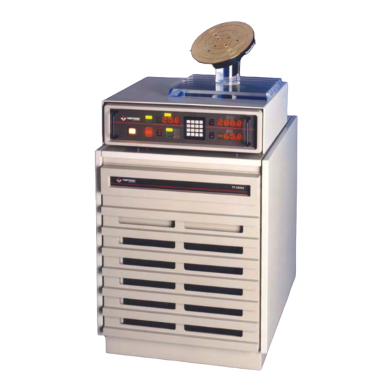
- Page 121 TP03000 Series ThermoChuck Systems ® System: • -65ºC to +200ºC extended temperature range with a low noise, DC control system. • Up to five temperatures and ramp/soak/cycle thermal cycling sets can be programmed at the front panel. • IEEE-488 and RS232 included. •...
- Page 122 TP03000 THERMOCHUCK SYSTEMS are essential for probing, characterization and failure analysis of wafers, individual chips and hybrids at temperatures required for commercial or MilSpec testing. SYSTEM TP03000 Systems consist of a controller, a stand-alone self- contained cooler/circulator and a temperature controlled vacuum chuck assembly.
- Page 123 SERIES ThermoChuck ® Systems Specifications - ThermoChuck Platform Diameter 103.1 mm, (4.06 inch) diameter ThermoChuck (wafers to 100 mm) 128.5 mm, (5.06 inch) diameter ThermoChuck (wafers to 125 mm) 154 mm, (6.06 inch) diameter ThermoChuck (wafers to 150 mm) 203 mm, (8.0 inch) diameter ThermoChuck (wafers to 200 mm) Temperature Uniformity ±0.5°C or ±0.5% of set temperature (whichever is greater)
- Page 124 41 Hampden Road, Mansfield, MA 02048 www.temptronic.com Interface Solutions Solutions TEL: +1.781.688.2300 4 Commercial Street Sharon, MA 02067 USA www.intest.com www.intest.com www.inTESTthermal.com Tel: (781) 688-2300 • Fax: (781) 688-2301 © Copyright, 2004 Temptronic Corporation. These specifications are valid for the standard product and are subject to change without notice. Applications requiring modification of electrical, thermal or mechanical characteristics should be discussed with the factory for possible accommodation at additional cost.
Need help?
Do you have a question about the Temptronic ThermoChuck TP03000 Series and is the answer not in the manual?
Questions and answers