
Subscribe to Our Youtube Channel
Related Manuals for Goodix GR5515

Summary of Contents for Goodix GR5515
- Page 1 GR5515 Starter Kit User Guide Version: 1.5 Release Date: 2020-05-30 Shenzhen Goodix Technology Co., Ltd.
- Page 2 Copyright © 2020 Shenzhen Goodix Technology Co., Ltd. All rights reserved. Any excerption, backup, modification, translation, transmission or commercial use of this document or any portion of this document, in any form or by any means, without the prior written consent of Shenzhen Goodix Technology Co., Ltd is prohibited.
-
Page 3: Preface
This document introduces the GR5515 Starter Kit (GR5515 SK), the hardware layout, the circuit schematics, hardware functional modules, and RF and current tests of the GR5515 Starter Kit Board (GR5515 SK Board), to help you get started with the GR5515 Starter Kit Board quickly in developing Bluetooth Low Energy (Bluetooth LE) products and applications with GR551x System on Chips (SoCs). -
Page 4: Table Of Contents
7 Buttons and LEDs ............................10 8 LCD Connector ............................11 9 On-board QSPI Flash ........................... 12 10 Performance Test ............................13 10.1 RF Test................................13 10.2 Current Consumption Test ..........................14 Copyright © 2020 Shenzhen Goodix Technology Co., Ltd. -
Page 5: Introduction
The GR5515 SK is a development platform based on GR551x SoCs (supporting Bluetooth 5.1). It contains a GR5515 SK Board, a schematic diagram, and a user guide. The GR5515 SK allows you to get familiar with GR551x-related development tools, quickly develop product prototype, and verify related functions. - Page 6 • SEGGER J-Link OB that supports debugging • UART-to-USB connector • Micro USB connector, which establishes connection between a GR5515 SK Board and a PC • 1.44-inch color TFT display • On-board QSPI flash Copyright © 2020 Shenzhen Goodix Technology Co., Ltd.
-
Page 7: Quick Start Guide
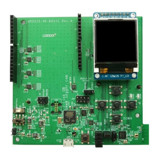
Arduino D102 Printed Antenna iPex Connector Micro USB Connector(J49) Figure 2-1 GR5515 SK Board assembly Before using a GR5515 SK Board, follow the steps below to configure power supply and establish connection: Copyright © 2020 Shenzhen Goodix Technology Co., Ltd. -
Page 8: Example Running
Quick Start Guide Connect the GR5515 SK Board to a PC with a Micro USB 2.0 cable. The Micro USB connector is used for power supply and programming through J-Link. Switch S6 (power switch) to the right side (as shown in the figure above) to power the board with current passing through the on-board LDO;... -
Page 9: Hardware Overview
Hardware Overview 3 Hardware Overview 3.1 Hardware Layout The top view and the bottom view of a GR5515 SK Board are shown in Figure 3-1 Figure 3-2 respectively. The board mainly integrates an interface microcontroller unit (MCU), a power module, Arduino Uno Shield Connectors, buttons and LEDs, a LCD connector, a Bluetooth LE RF module, and an on-board QSPI flash. -
Page 10: Block Diagram
Hardware Overview Lithium battery On-board QSPI Flash Figure 3-2 Hardware layout of GR5515 SK Board (bottom view) 3.2 Block Diagram The following block diagram of a GR5515 SK Board shows connections between modules. GPIO/Arduino Uno Level shift External supply Battery... -
Page 11: Interface Mcu
GPIO11 4.3 Software Download Port of Interface MCU The J-Link port, J43, on the GR5515 SK Board is used for SEGGER J-Link OB firmware download for interface MCU. Note: GR5515 SK Boards have been factory-programmed with J-Link OB firmware. No programming is required for users. -
Page 12: Power Supply
Power Supply 5 Power Supply The GR5515 SK Board provides three power supply modes: power supply via USB connection, power supply from external sources and from lithium battery. Power supply from Power supply via USB external sources connection Figure 5-1 Power supply (top view) - Page 13 You can switch S6, to select the power supply mode (from lithium battery or the 3.3 V power output by the on-board LDO). Reverse voltage protection is provided for power supply via USB connection and from external sources through a pair of diodes (D100 and D105). Copyright © 2020 Shenzhen Goodix Technology Co., Ltd.
- Page 14 Power Supply Figure 5-3 Voltage protection diodes for power supply via USB connection/from external sources Copyright © 2020 Shenzhen Goodix Technology Co., Ltd.
-
Page 15: Arduino Uno Shield Connectors
Arduino Uno Shield Connectors 6 Arduino Uno Shield Connectors The GR5515 SK Board provides standard Arduino Uno Shield Connectors, and the connector locations on the SK printed circuit board (PCB) comply with Arduino standards. You can connect peripherals, such as G-sensor and heart rate sensor, through Arduino Uno Shield Connectors. -
Page 16: Buttons And Leds
Buttons and LEDs 7 Buttons and LEDs The GR5515 SK Board integrates 6 buttons and 3 LEDs, with corresponding GR551x pins as follows: Table 7-1 Corresponding pins to buttons/LEDs Button/LED GPIO Pin Description Note Button1 GPIO14 S3 (LEFT) Button2 GPIO15... -
Page 17: Lcd Connector
8 LCD Connector The GR5515 SK Board integrates a color TFT LCD display (1.44 inch, 128 x 128 dpi) and a 3-wire serial peripheral interface (SPI), to help you develop and demonstrate products with display function. In addition, the LCD display is pluggable. -
Page 18: On-Board Qspi Flash
To use QSPI flash pins, disconnect these pins from buttons, GPIO8, and GPIO9, and solder a zero-ohm resistor at the corresponding DNI resistance part. Figure 9-2 Connections shared by buttons and QSPI flash pins Copyright © 2020 Shenzhen Goodix Technology Co., Ltd. -
Page 19: Performance Test
10 Performance Test 10.1 RF Test The GR5515 SK Board reserves a small RF connector (J50), which can be connected to a spectrum analyzer or a Bluetooth LE tester (for example, TLF3000) to test the RF performance of the GR5515 SK Board. -
Page 20: Current Consumption Test
10.2 Current Consumption Test You can test the current consumption of the GR551x SoC on the GR5515 SK Board with a test instrument. On the board, VBAT powers VBATH, VBATL, and VBAT-RF of the GR551x SoC through the jumper pin J10. Therefore, you can connect a test instrument to J10 to test the current. - Page 21 10-3. During a Bluetooth LE event, the power analyzer automatically stores and displays current curve changes for the moment. You can zoom in the curves to see current consumption details. For more information, see operational instructions of the power analyzer. Copyright © 2020 Shenzhen Goodix Technology Co., Ltd.
Need help?
Do you have a question about the GR5515 and is the answer not in the manual?
Questions and answers