Advertisement
Table of Contents
- 1 Table of Contents
- 2 Chapter 1: Computer Requirement
- 3 Chapter 2:Installation
- 4 Chapter 3:Characteristic
- 5 Chapter 4:Board System
- 6 Chapter 5:Software Installation
- 7 Chapter 6:Software Interface
- 8 Chapter 7: Software Calibration
- 9 Chapter 8: Other Functions and Parameters
- 10 Chapter 9: Maintenance
- 11 Chapter 10: Troubleshoot
- 12 Chapter 11: Output Chart
- Download this manual
Advertisement
Table of Contents

Summary of Contents for Galaxy DX5
- Page 1 Galaxy DX5 X 1 Printhead Calibration and Maintenance July, 2015 Version V3.0...
-
Page 2: Table Of Contents
Contents Chapter 1: Computer Requirement ..............3 Chapter 2:Installation..................4 Chapter 3:Characteristic...................5 Chapter 4:Board System.................6 Chapter 5:Software Installation ..............7 Chapter 6:Software Interface................9 Chapter 7: Software Calibration..............10 Chapter 8: Other Functions and Parameters ..........14 Chapter 9: Maintenance..................16 Chapter 10: Troubleshoot................21 Chapter 11: Output Chart.................22... -
Page 3: Chapter 1: Computer Requirement
Chapter 1: Computer Requirement 1) Basic requirement: - CPU: Intel(R) Core(TM)2 Duo CPU E4600 @ 2.4GHz - Memory: 2GB or higher - Hard disk: 200 GB (NTFS format, recommend 20GB free space) - Mother board: USB 2.0 connection equipped - Network card - Operating system: Microsoft Windows (XP, 7, 8) 2) Recommendatory requirement: - CPU: Intel(R) Core(TM) I3-2120 @ 3.10 GHz or higher... -
Page 4: Chapter 2:Installation
Chapter 2: Installation 1) Move the packing box to the working site and avoid strong shaking. 2) Disassemble the wooden packing box from top to bottom. Check whether the parts are complete or not according to the packing list. 3) Lift the printer out by a forklift, and move it to the installation site. 4) Check if the printer is level. -
Page 5: Chapter 3:Characteristic
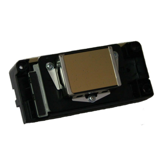
Chapter 3: Characteristics Printhead: 1pc (Epson DX5) Resolution: 1440\1080\720DPI Color: 4 colors Print mode: 3,4,6,8,12 Pass Output mode:File or TCP/IP(Rip and Print at the same time) Output preview:Convert prn/prt file into a small bmp file for previewing ... -
Page 6: Chapter 4:Board System
Chapter 4: Board System Printhead Board Processing Power flat Power LED Encoder sensor Magnetic sensor Indication cable plug Status LED Optical Fiber plug Printhead cable Printhead cable plug 2 plug 1 Main Board Power supply Pump plug X Driver DB plug Y Driver DB plug plug Processing Indication... -
Page 7: Chapter 5:Software Installation
Note: 1. After turning on the machine till the carriage moving back to home position, the processing indication shows as: A. – 1 – 3– 4– 5 – 0. Main board and Head board show the same indication. 2. The two power cable plug both are 20Pin. 3. -
Page 9: Chapter 6:Software Interface
Chapter 6. Software Interface 1) Introduction: ouble click to open the software. Configuration definition: UDT_LC_LD_1H : LC or LD model with 1 printhead. UDT_LC_LD_2H : LC or LD model with 2 printheads. Tools bar Directory of printing jobs Jobs print Preview Image information... -
Page 10: Chapter 7: Software Calibration
Chapter 7. Software Calibration 1. Nozzle checking: Print the nozzle checking to check the condition of the printhead. Make sure to turn off the Eclosion (Feather) function before doing the alignment. 2. Vertical calibration: Observe the physical alignment of printheads. (This step is not aligned well which will affect the following adjustment)... - Page 11 3) The second is on the right side of the first pass: Second pass First pass Adjust method: B. Turn the screw anti-clockwise: A. Loosen the 3 screws on the carriage plate: Note: Every time after the adjustment, before print another vertical calibration, it is required to tighten 3 screws on the carriage plate.
- Page 12 After input the value, print the alignment again. And observe if the "0" position is the best or not. If not, repeat the above procedure until the best result come out. 4. Bi-Dir offset Bi-Dir offset is to make sure there is no bi-difference while using different speed to print. Bi-Dir offset will be set for different printing speed.
- Page 13 Have to input +2. Based on the "0" position, input the value which two line are perfectly overlapped. After input the value, test again to check the result. The step value will be different according to different media. Note: Turn off the Eclosion (Feather) function first while adjusting the step offset. Adjust to get the best step value.
-
Page 14: Chapter 8: Other Functions And Parameters
Chapter 8. Other Functions and Parameters 1 Printhead voltage Normally the voltage function is not being used. The range of adjusting voltage is -42V to +1.3V. 2. Other function Click Option on the main interface of the software, it shows the following window: Details of the print option: 1. - Page 15 2. Clean Option: 1) Click to set the carriage go back to the flash jetting position for jetting during printing; 2) Print pass is to set every XX pass, carriage go back to the flash jetting position for jetting; 3) Clean Mode is Flash Jetting; 4) There are three options in Clean Time, Fast means non-stop jetting, Normal means jetting for 0.5s, , Long means jetting for 1s.
-
Page 16: Chapter 9: Maintenance
Chapter 9. Maintenance 9.1 Normal Cleaning Click Clean on the main interface of the software. There are two modes of cleaning, Standard and Depth. Normally Standard mode is used. 9.2 Cleaning procedures for nozzle clogging: 1. Disconnect the tube connector for the tube from cartridge to the damper. Choose Standard clean mode the suck out the ink in the damper. - Page 17 9.4 Daily Maintenance 1. Print the nozzle checking before turn off the machine to make sure the printhead is in normal condition 2. Turn off the software, carriage go back to Home position automatically. Turn off the machine, the carriage stay at the Home position.
- Page 18 4. Take out the extend tube from the Flush, and keep it out in the air. Choose Depth clean mode to empty the Flush inside the damper and the printhead. 5. Take out the four tubes(K,C,M,Y) from the cartridge. Use the extend tube to connect them to flush.
- Page 19 Use a extend ink tube to connect the ink tube to ink pump Choose “Ink Fill” mode at control panel, use ink pump to flush ink tube until it is clear. Then take out the tube from the Flush, choose “Ink Fill” mode, empty the Flush inside the ink tube. Clean K,C,M,Y tube one by one After cleaning, use cap and fresh warp to seal the ink tubes.
- Page 20 6. Take out four cartridges, use fresh wrap to seal the ink supply hole and keep the cartridges in the proper place. Keep the carriage back to Home position and make sure the cap is perfectly sealing the printhead.
-
Page 21: Chapter 10: Troubleshoot
Chapter 10. Troubleshoot 10.1 Turn on the machine and carriage reposition normally. Turn on PrintExp and then : show a note of Initialize the printer failed or Machine model incorrect 1) Check USB data cable connection, whether damage or not.; 2) Check whether the USB driver is installed properly;... -
Page 22: Chapter 11: Output Chart
Chapter 11.Output Chart Output Chart Printhead Epson DX5 Number of printhead Fast mode output(m Print Mode 1.6m 1.8m 2.1m 2.5m Draft 4Pass Output Standard 6Pass Quality 8Pass High Quality 8Pass Back lit 12Pass ***The speed data are taken from the printer at the high speed level;...