Table of Contents
Advertisement
Advertisement
Table of Contents

Related Manuals for CASTLE EURO mini

Summary of Contents for CASTLE EURO mini
- Page 1 I n s t a l l a t i o n M a n u a l EN50131-1 RINS1211-9...
-
Page 3: Table Of Contents
External Reader Connection Double Pole - Alarm Connections Double Pole - Tamper Connections DEOL: 4K7 Alarm, 2K2 Tamper DEOL: 4K7 Alarm, 4K7 Tamper Siren Connection Speaker Connection Output Connection/Example Compliance Statement and Warranty Compliance Statement Warranty Input Table Appendix Castle Page:3... -
Page 4: System Overview
Contemporary LCD Keypad 32 Character Number of Keypads Arming Options Timed, Final Door, Timed/Final User Codes 30 user codes, 1 Master Manager, 1 Engineer Logs 500 Mandatory, 200 Optional Fuses AUX, Bell, RS485 Bus, Battery Tampers Case Tamper and Siren Tamper Page:4 Castle... -
Page 5: Technical Specification
Mains Fuse Mains Fuse - Anti-Surge 315mA Physical/Mechanical Specification Dimensions 250 x 297 x 82mm Weight 3.07 kilos Environmental Specification Operational temperature -20°C to +60°C range Storage temperature -20°C to +60°C range Battery recommend 3Ah or 7Ah (Max) Castle Page:5... -
Page 6: Overview
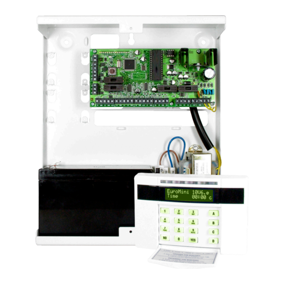
Control Panel The EURO mini is already fully assembled in a metal case. The diagram below shows a basic overview of the different components. The Control Panel Page:6 Castle... -
Page 7: The Printed Circuit Board
Printed Circuit Board The EURO mini printed circuit board is as follows: The Printed Circuit Board Power LED Fuses (flashes) BELL Fuses BATTERY Remove for DP Z1 COM Z2 0V +12V Z3 COM Z4 Z5 COM 0V +12V Z7 COM... -
Page 8: The Tamper Spring And Connections
Tamper Connections The EURO mini printed circuit board is protected by a metal casing. The lid is tampered by a spring that is connected to the printed circuit board. To disable the tamper spring, simply link out the tamper connections shown below. -
Page 9: Connections
The transformer will be factory fitted to the connections shown below on the EURO mini. It is recommended that a 3Ah or 7Ah battery should be used on the EURO mini. This connects to the Battery positive and negative terminals. -
Page 10: Keypad Connection
Contemporary Keypad A maximum of 4 keypads may be installed to the EURO mini. Each keypad (EUR-068 or EUR-069) connects to the RS485 terminal: D1-, D2+, D3 and D4. Each keypad must be individually addressed, starting with 00. To do this, press and hold the ‘D’... -
Page 11: Reader Connection
Internal Tag Reader A maximum of 3 readers may be installed to the EURO mini if the EUR-068 is installed. Each connect to the RS485 terminal: D1-, D2+, D3 and D4. Each reader must be individually addressed, starting with 01. To do this, there are dip switches on the back of the reader. -
Page 12: External Reader Connection
External Tag Reader A maximum of 3 readers may be installed to the EURO mini if the EUR-068 is installed. Each connect to the RS485 terminal: D1-, D2+, D3 and D4. Each reader must be individually addressed, starting with 01. To do this, certain... -
Page 13: Double Pole - Alarm Connections
(When a clean start 2002 is performed, input 1 is defaulted as tamper). The first diagram below shows the connection of door contacts/detectors to the EURO mini, the second diagram shows how the tamper circuits of each detector should be connected. The diagrams are split for clearer wiring connections. -
Page 14: Deol: 4K7 Alarm, 2K2 Tamper
Input 1 Input 2 BELL Door Contact Detector DEOL: 4K7 Alarm, 4K7 Tamper BATTERY Remove for DP This link should be ON +12V GND +AUX- ALARM TAMPER Spare N/C Contact Input 1 Input 2 Door Contact Detector Page:14 Castle BELL... -
Page 15: Siren Connection
Bell Tamper Bell Trigger Strobe Trigger Speaker Connection BELL BATTERY BELL Remove for DP BATTERY Remove for DP 1 or 2 16ohm speakers may be wired in parallel 1 or 2 16ohm speakers may be wired in Castle Page:15 parallel... -
Page 16: Output Connection/Example
Output Connections The EURO mini supports up to 7 outputs. 4 of the outputs are shared with inputs on the system, therefore if the outputs are used (see Change Outputs in the programming manual), inputs 7 to 10 become disabled. All outputs on the system are negative applied and cannot be altered. -
Page 17: Compliance Statement And Warranty
Statement and Warranty Compliance Statement The EURO mini complies with the requirements of the EMC Directive (2004/108/ EC) and the Low Voltage Directive (2006/95/EC). The EURO mini complies with EN50131-3:2009 Suitable for use in systems installed to PD6662:2010 at security grade 1 or 2X and environmental class 2. -
Page 18: Input Table Appendix
Table Appendix Input Input Type Input Areas Description Number Page:18 Castle... - Page 19 Castle Page:19...
- Page 20 Contact Details Castle Secure House Braithwell Way Hellaby Rotherham S66 8QY Customer Support: +44(0)845 6434 999 (local rate) Or telephone: +44(0)1709 535225 Opening Hours: 8.00am - 6.30pm Monday to Friday E-mail: support@castle-caretech.com Website: www.castle-caretech.com...
Need help?
Do you have a question about the EURO mini and is the answer not in the manual?
Questions and answers