
Subscribe to Our Youtube Channel
Related Manuals for Sensata Magnum Energy ME-RC

Summary of Contents for Sensata Magnum Energy ME-RC
- Page 1 ME-RC Standard Remote Control Owner’s Manual (Revision 2.9 or higher: includes AGS & BMK info)
- Page 2 Thank you from all of us at Sensata Technologies for purchasing this ME-RC remote. The ME-RC is a product under the Magnum Energy brand from Sensata. We understand there are many purchasing options in the marketplace, and are pleased that you have decided on a Magnum product.
- Page 3 AC - turning off the inverter may not reduce this risk. As long as AC power is connected, it will pass thru the inverter regardless of the power switch on the inverter or the ON/OFF INVERTER button on the remote. © 2020 Sensata Technologies...
-
Page 4: Table Of Contents
LED Indicator Guide ............57 ME-RC Remote Troubleshooting ........58 Inverter/Charger Troubleshooting Tips ........59 6.1.1 Inverter Problems ............... 59 6.1.2 Charger Problems ............... 59 Performing an Inverter Reset ..........60 Performing a Power Reset ............. 60 © 2020 Sensata Technologies... - Page 5 Table 7-1, ME-RC Autostart/Autostop Matrix ........61 Table 7-2, Battery AmpHrs Capacity to Suggested Gen Run Time ... 62 Table 7-3, AGS Remote Operational Statuses........71 Table 7-4, AGS Remote Start Statuses ..........72 Table 7-5, AGS Remote Fault Statuses ..........72 © 2020 Sensata Technologies...
- Page 6 Figure 8-1, Accessing the BM Setup Menu ........... 76 Figure 8-2, Changing the Charge Effi ciency Setting ......77 Figure 8-3, Adjusting the AmpHour Size ..........78 Figure 8-4, ME-RC50 METER Menu Map (Displays w/BMK Settings) ..79 © 2020 Sensata Technologies...
-
Page 7: Introduction
Pushing this rotary knob allows you to select a menu item, or to save a setting once it is displayed on the LCD. © 2020 Sensata Technologies... -
Page 8: 2.0 Installation
ME-RC Owner’s Manual If items appear to be missing or damaged, contact your authorized Magnum Energy product dealer or Sensata Technologies. Save your proof-of-purchase as a record of your ownership; it is needed if the unit should require in- warranty service. -
Page 9: Connecting The Remote Cable
REMOTE (blue) port on the Magnum inverter/charger (see Figure 2-2). Note: Connect the remote cable after mounting the remote as described in Section 2.4. Large Magnum inverters Small Magnum inverters ME-RC ME-RC remote remote (back) (back) Figure 2-2, Remote Control Connections © 2020 Sensata Technologies... -
Page 10: Me-Rc Remote Dimensions
CAUTION: Always check for hidden electrical wires, pipes and cables BEFORE drilling, cutting, or screwing into walls or cabinets. Info: The ME-RC can be surface mounted on a wall using the optional ME-BZ (remote bezel). © 2020 Sensata Technologies... -
Page 11: Flush Mount Installation Procedure
If the self test is successful, secure the ME-RC to the wall using the four supplied Phillips screws. If the self test is unsuccessful, refer to the Troubleshooting section. 5.0" (12.7 cm) 3.0" (7.6 cm) Figure 2-4, Flush Mounting the ME-RC © 2020 Sensata Technologies... -
Page 12: Power-Up Self Test
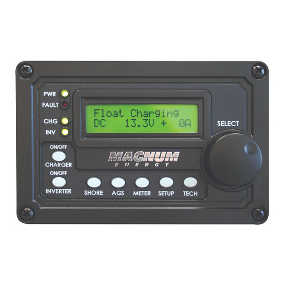
ME-RC’s home screen (see example below). FAULT Inverting 25.2V - 10A Top line: Current status of inverter Bottom line: Voltage from the batteries connected to the inverter, and the battery current used by the inverter Figure 2-6, Example: ME-RC Home Screen © 2020 Sensata Technologies... -
Page 13: Setup
Info: Hold down the SELECT button for 10 seconds to refresh the LCD display. Inverting DC: 12.6V Menu Rotary LCD Display Buttons SELECT Knob Figure 3-1, Front Panel Setup Features © 2020 Sensata Technologies... -
Page 14: Figure 3-2, Setup Menu Navigation
Rotate the SELECT knob to the desired setting. When the bottom line shows the Inverting desired setting: BatType= AGM 1 5. Press the SELECT knob to save this setting. Figure 3-2, SETUP Menu Navigation © 2020 Sensata Technologies... -
Page 15: Remote Feature To Inverter Compatibility
05 Start Start OFF, 10.0 - 12.2* ≥Level 1 11.0 Volts VDC= Hour= 01:xxx-12:xxx 06 Set Minute= xx:00x-xx:59x ≥Level 1 12:00A Time AM-PM= xx:xxA-xx:xxP OFF, 07 Quiet Quiet= 9PM- (7AM/8AM/9AM), ≥Level 1 Time (10PM/11PM) - 8AM © 2020 Sensata Technologies... - Page 16 ≥Level 1 [5] Read Only Read only display 06 BM: Min DC: ≥Level 1 [5] Read Only (press SELECT to reset) TECH Read only display Max DC: ≥Level 1 [5] Read Only (press SELECT to reset) © 2020 Sensata Technologies...
- Page 17 ≥Level 1 80 VAC UPS Mode Dropout= 06 VAC Export Models: 110 - 190 ≥Level 1 150 VAC Dropout VAC, UPS Mode Drop- US Models: 60 - 100 VAC, Dual-source 80 VAC out2= UPS Mode Models only © 2020 Sensata Technologies...
- Page 18 1.5 to 6.5 hours; any setting outside these limited ranges are not recognized and reverts to the inverter’s default absorption time (2.0 hours). [5] BM/SOC features require the ME-BMK (Battery Monitor Kit) to be installed. © 2020 Sensata Technologies...
-
Page 19: Remote Buttons And Menu Items
SHORE Shore Max =**A The left facing arrow in Rotate to this display shows the Press desired Press to save selected setting that has selection: been saved. Range: 5-60 Amps Figure 3-3A, SHORE: Shore Max Selection © 2020 Sensata Technologies... -
Page 20: Figure 3-3B, Shore: Shore Max2 (Dual-Source Models Only)
1/3 of the generator’s rated capacity, and then while the generator is heavily loaded, gradually increase the setting as high as possible while ensuring the generator’s output voltage level stays above the SETUP/06 VAC Dropout setting. © 2020 Sensata Technologies... -
Page 21: Ags Menu
Info: Refer to Section 7.0 (in this manual) and to your ME-AGS-N Owner’s Manual (PN: 64-0039) for detailed information on the AGS. Status... 01 AGS Control SHORE METER SETUP TECH Press Figure 3-4, AGS Menu Display © 2020 Sensata Technologies... -
Page 22: Meter Menu
When in Standby mode, this meter displays the frequency of the incoming AC source (i.e., grid or generator) that is passing through the inverter to the inverter’s output terminals. The frequency value is shown in Hertz (Hz). © 2020 Sensata Technologies... - Page 23 Example: If the charger is delivering 20A to the battery from the AC source and the load connected to the inverter output is using another 10A, the combined load on the incoming AC source is 30A. So the Input Amps display would show 30A. © 2020 Sensata Technologies...
-
Page 24: Figure 3-6, Current Flow - Inverter Mode
Current from battery (I/C Amps) = -10 Amps AC Current to power the AC loads (Load Amps) = 10 Amps AC [Status/Fault] [Status/Fault] [Status/Fault] Input Amps: 0AAC I/C Amps: -10AAC Load Amps: 10AAC Figure 3-6, Current Flow – Inverter Mode © 2020 Sensata Technologies... -
Page 25: Figure 3-7, Current Flow - Standby Mode
Current from battery (I/C Amps) = -10 Amps AC Current to power the AC loads (Load Amps) = 20 Amps AC [Status/Fault] [Status/Fault] [Status/Fault] Input Amps:10AAC I/C Amps: -10AAC Load Amps: 20AAC Figure 3-8, Current Flow – Load Support Mode © 2020 Sensata Technologies... -
Page 26: Setup Menu
Search Watts setting until the load comes on and stays on. Info: Even though the Search feature is on, some connected equipment—even if they are off—may draw enough current to keep the inverter in the Inverting mode (i.e., not “Searching”). © 2020 Sensata Technologies... -
Page 27: Figure 3-10, Setup: 02 Lowbattcutout Selections (12V)
LBCO Fault. Info: If there is an AGS-N installed, it should be set to start ≥1.0 volts higher than the LBCO setting—this is to prevent the inverter from shutting down before the generator comes on. © 2020 Sensata Technologies... -
Page 28: Table 3-2, Battery Amphrs Capacity To Suggested Absorb Time
200-300 60 minutes 1310-1500 240 minutes 310-500 90 minutes 1510-1700 270 minutes 510-700 120 minutes 1710-1900 300 minutes 710-900 150 minutes 1910-2100 330 minutes 910-1100 180 minutes 2110-2300 360 minutes 1110-1300 210 minutes 2310-2500 390 minutes © 2020 Sensata Technologies... -
Page 29: Table 3-3, Battery Size To Battery Amphrs (Estimated)
‘series string’ and the amp-hour capacity doesn’t change. Each series string is connected together in parallel to increase the amp-hour capacity. Add the amp-hour capacity of each series string connected in parallel to determine the total amp-hour capacity of the battery bank. © 2020 Sensata Technologies... -
Page 30: Figure 3-12, Setup: 04 Battery Type Selections
BMK (under METER: 03 BM: Meters/DC Amps) will be used by the CC/CV’s Max Amps setting instead of the inverter’s DC calculated current (shown under METER: 01A INV/ CHG Meter/ DC:)—as it is more accurate (+/- .1 ADC). © 2020 Sensata Technologies... - Page 31 Default: 20 ADC Range: 0-250 ADC Info: Setting the DoneAmps value to zero keeps the charger in the Constant Voltage charge mode until the MaxTime setting (under SETUP: 04 Battery Type/CC/CV) is reached. © 2020 Sensata Technologies...
- Page 32 Range: 12.0-16.0 VDC (12v), 24.0-32.0 VDC (24v), 48.0-64.0 VDC (48v). Hold VDC – This setting holds the battery voltage at the Chg Volts setting. This is for a system that requires a constant charge voltage to be present at all times (see Figure 3-14). © 2020 Sensata Technologies...
-
Page 33: Figure 3-13, Done Time/Amps Charge Stages
(= Time or Amps) Recharge Volts (restarts Constant Current charge) Current Voltage TIME Figure 3-13, Done Time/Amps Charge Stages Constant Constant Voltage Current CV Charge Max Amps Volts Hold VDC Current Voltage TIME Figure 3-14, Hold VDC Charge Stages © 2020 Sensata Technologies... - Page 34 Info: The LFP battery type selection forces the charger to go into the Bulk charge mode each time AC is connected. If AC is reconnected less than two minutes after being disconnected, the charger will return to the previous charge mode. © 2020 Sensata Technologies...
-
Page 35: Table 3-4, Battery Type To Charge Voltages
BTS is below 77° F (25° C), and decrease if higher than 77° F (25° C). This ensures the batteries receive the correct charge voltage regardless of temperature. © 2020 Sensata Technologies... -
Page 36: Figure 3-15, Setup: 05 Charge Rate Selections
* C/5 or C/20 rate – charge rates are commonly expressed as a ratio of the total amp-hour (AH) capacity of the battery bank. For example, with a 400 AH battery bank (C = 400), the C/5 charge rate is 80 A (400/5 = 80 A). © 2020 Sensata Technologies... -
Page 37: Figure 3-16, Setup: 06 Vac Dropout Selections
fl uctuations. This setting is intolerant of voltage fl uctuations, so the UPS Mode setting is not recommended when using a generator as your AC source. The transfer time from Charge mode to Inverter mode is ≤16 milliseconds when using this setting. © 2020 Sensata Technologies... -
Page 38: Figure 3-17, Setup: 07 Power Save Selections
Press to select selection: 08 Screen Setup Contrast Range: 0-100% (increments by 10%) Status... Brightness =50% Rotate to desired Press to save selection: Brightness Range: 0-100% (increments by 10%) Figure 3-18, SETUP: 08 Screen Setup Selections © 2020 Sensata Technologies... -
Page 39: Figure 3-19, Final Charge Stage - Multi-Stage
Absorb Amps Volts Volts Absorb Done (= Time, Amps 4 Hours or SOC) ReFloat Volts (restarts Float Charge for 4 hours, then back to Full Charge) Current Voltage TIME Figure 3-19, Final Charge Stage - Multi-Stage © 2020 Sensata Technologies... -
Page 40: Figure 3-20, Final Charge Stage - Float Stage
First Stage Second Stage Final Stage Bulk Charging Absorb Charging Float Charging Max Charge Absorb Amps Volts Float Absorb Done Volts (= Time, Amps or SOC) Current Voltage TIME Figure 3-20, Final Charge Stage - Float Stage © 2020 Sensata Technologies... -
Page 41: Figure 3-21, Final Charge Stage - Silent Stage
First Stage Second Stage Bulk Charging Absorb Charging Silent Max Charge Absorb Amps Volts Absorb Done (= Time, Amps or SOC) Rebulk Volts (restarts Bulk Charging) Current Voltage TIME Figure 3-21, Final Charge Stage - Silent Stage © 2020 Sensata Technologies... - Page 42 Enabling the Always Bulk setting will force the charger to automatically go into the Bulk charge mode and go through a full charge each time AC is connected to the inverter’s AC input. © 2020 Sensata Technologies...
-
Page 43: Tech Menu
“0.0” revision. If this happens, then the accessory is not installed, there is no communication because of a bad or miswired network cable, the device is not powered, the device is bad, or the port on the inverter is bad. © 2020 Sensata Technologies... -
Page 44: Figure 3-24, Tech: 03 Inv Model Display
TECH Factory defaults are loaded and display shows: Rotate to Press Status... Status... Press and hold 04 Load Defaults DEFAULTS LOADED for 5 seconds Figure 3-25, TECH: 04 Load Defaults Selection © 2020 Sensata Technologies... -
Page 45: Table 3-5, Me-Rc's Inverter/Charger Default Settings
* - If using a dual-source model inverter (which has two AC source inputs), both the AC1 and AC2 inputs have the same default setting. The Shore Max = 30A, and VAC Dropout = 80 VAC). © 2020 Sensata Technologies... -
Page 46: Figure 3-26, Tech: 05 Ext Control Display
Unlock Setup – Press SELECT to allow all users to access the SETUP button menus. Lock Setup – Press SELECT to restrict access to the SETUP button menus to only those users with the valid PIN. Change PIN – Press SELECT to change the existing PIN. © 2020 Sensata Technologies... - Page 47 Resetting/Clearing a PIN You can override a previously entered PIN. When “PIN = 0***” displays, press and hold the SELECT knob until “PIN = 0000” displays (approximately 7 seconds). Enter a new PIN number as previously described. © 2020 Sensata Technologies...
-
Page 48: Menu Map: Me-Rc Remote Control
* LBCO settings are dependent on inverter model (values for a 12-volt model shown) Stat us... Stat us... 0.1-25.5 Hrs 03 Abso rb Time Abso rb Hrs= 1.5 SETUP menu continues on next page Figure 4-1, Inverter/Charger Menu Map © 2020 Sensata Technologies... -
Page 49: Figure 4-2, Inverter/Charger Menu Map
12 .0V* Stat us... Stat us... NO, YES 10 P wr Up Al ways Pwr Up = Stat us... Stat us... ON, OFF 11 B ulk Alwa ys Bulk Always= OFF Figure 4-2, Inverter/Charger Menu Map © 2020 Sensata Technologies... -
Page 50: Figure 4-3, Inverter/Charger Menu Map
01 Sear ch Watts Press SELECT Inverter/Charger Status Stat us... Menu Selections Setting Sear ch = 5W Notes: = setting range = default setting = Rotate SELECT knob ## = read only data Figure 4-3, Inverter/Charger Menu Map © 2020 Sensata Technologies... -
Page 51: 5.0 Operation
SETUP menu. This display automatically powers-up with the current system status on the top line and the home screen (detailing the inverter’s DC voltage and current as shown in Figure 5-1) on the bottom line. © 2020 Sensata Technologies... -
Page 52: On/Off Pushbuttons
AGS menu, and SETUP menu’s 08 Screen Setup settings (which all revert back to default) are saved in non-volatile memory and are preserved until changed—even if an inverter reset is performed, or if all power to the remote or inverter is removed. © 2020 Sensata Technologies... -
Page 53: Operating The Inverter/Charger
AGM types could permanently damage them. Refer to your battery manufacturer on how to properly equalize your batteries. Info: Equalization charging is not available if GEL, AGM2, or LFP is selected under the SETUP menu’s 04 Battery Type menu. © 2020 Sensata Technologies... -
Page 54: System Status Messages
• Internal Relay • Load Support VDC • Low Battery • Silent • Overcurrent • Overtemp • StackClock Fault • Stack Mode Fault • StackPhase Fault • Stuck Relay • Tfmr Overtemp • Unknown Fault ## © 2020 Sensata Technologies... -
Page 55: Inverter Mode Status Messages
Unknown Mode ## – This status displays when the inverter/charger has sent an operational status code that the RC remote does not identify. Remedy: Call Technical Support at Sensata Technologies for assistance in identifying and understanding the actual status. 5.3.2... - Page 56 This charge stage continues until the EngChg setting (Time, Amps, or Hold) or MaxTime settings under the SETUP button’s 04 Battery Type: CC/ CV menu) is reached. Note: This status only displays if “CC/CV” has been selected from the SETUP button’s 04 Battery Type menu. © 2020 Sensata Technologies...
- Page 57 04 Battery Type setting as shown in Table 3-4. Info: Unless the Silent mode is enabled, when the battery voltage falls ≤12.1 VDC (12-volt models), ≤24.2 VDC (24-volt models), or ≤48.4 VDC (48-volt models) the unit will initiate bulk charging. © 2020 Sensata Technologies...
- Page 58 ReBulk voltage setting (from 09 Final Charge Stage menu) the charger will restart a Bulk and Absorb charge cycle, and then transition back into Silent mode at the end of the Absorb cycle. © 2020 Sensata Technologies...
-
Page 59: Fault Mode Messages
This fault automatically clears if the AC input power is removed or when the voltage is greater than 12.6 volts (12-volt models), 25.2 volts (for 24-volt models), or 50.4 volts (for 48-volt models) as detected by the inverter. © 2020 Sensata Technologies... - Page 60 AC input. Remedy: Remove all AC power from the inverter’s AC input for at least 15 minutes to automatically reset this fault. Ensure only 120VAC power is connected to each of the inverter’s AC inputs. © 2020 Sensata Technologies...
- Page 61 If it occurs when charging, lower the charge rate. If this fault happens often, ensure the inverter is not in a hot area, has proper ventilation, and the cooling fans inside the inverter are working. © 2020 Sensata Technologies...
- Page 62 • Unknown Fault ##– This fault message displays when the inverter/ charger has sent a fault code that cannot be determined by the remote. Remedy: Contact the Magnum Technical Support team to assist you. © 2020 Sensata Technologies...
-
Page 63: Led Indicator Guide
CHG LEDs are on); the inverter will automatically (green) supply AC power to the loads if shore or generator power is lost. Inverter is in Search mode (the AC load is below BLINKING the SETUP menu’s 01 Search Watts setting). © 2020 Sensata Technologies... -
Page 64: Me-Rc Remote Troubleshooting
Inverter is not Ensure inverter batteries connected to connected inverter batteries. operating correctly without any AC power connected (can invert and power AC loads from batteries). © 2020 Sensata Technologies... -
Page 65: Inverter/Charger Troubleshooting Tips
Temperature Sensor (BTS) temperature. If the BTS is installed, the charge voltage settings will increase if the temperature around the BTS is below 77° F (25° C), and will decrease if the temperature around the BTS is higher than 77° F (25° C). © 2020 Sensata Technologies... -
Page 66: Performing An Inverter Reset
Info: If DC disconnects are not used, there may be a momentary spark when the positive battery cable is connected to the inverter’s terminal. This is normal and indicates that the inverter’s internal capacitors are being charged. © 2020 Sensata Technologies... -
Page 67: 7.0 Using An Ags
03 Run Time Hour temperature, or (page 62) set time period, or (page 62) Gen starts on low 05 Start Volts Gen stops at Quiet 07 Quiet Time inverter battery (page 63) Time (page 64) voltage © 2020 Sensata Technologies... -
Page 68: Table 7-2, Battery Amphrs Capacity To Suggested Gen Run Time
AGS: 03 Run Time Hour setting. When this run time period is fi nished, the temperature sensor reading is checked. If the temperature sensor (or thermostat control—if using the optional pigtail adapter) reading is below the AGS: 04 Start Temp F setting, the generator will autostop. If the temperature © 2020 Sensata Technologies... - Page 69 Time Hour setting. If the DC voltage start feature is not needed, ensure this setting is set to the OFF position. Default setting: Start VDC = 11.0 VDC (12v), 22.0 VDC (24v), 44.0 VDC (48v) Range: 10.0-12.2 VDC (12v), 20.0-24.4 VDC (24v), 40.0-48.8 VDC (48v) © 2020 Sensata Technologies...
- Page 70 Quiet Time—which would allow the generator to run at any time in a 24-hour period. Where should I set Quiet Time? Select the time period that coincides with any local noise requirements, or any time period that you do not want the generator to automatically run. © 2020 Sensata Technologies...
-
Page 71: Ags Functional Tests
AGS and the generator. 7.3.1 Controlling the AGS using the ME-RC Press the AGS button, and then rotate and press the SELECT knob to access the following menus: © 2020 Sensata Technologies... -
Page 72: Monitoring The Ags Using The Me-Rc
AGS installation. Info: For any fault mode displayed in the status menu, please refer to Section 7.8.3 “Resolving Fault Statuses” in this manual. Note: AGS menus 03-07 were covered in Section 7.1. © 2020 Sensata Technologies... - Page 73 AGS system is not needed, the “Other” setting can be chosen. When the AGS is in the “Other” mode, manually turning the generator off or on will not automatically disable the AGS system. © 2020 Sensata Technologies...
-
Page 74: Enabling The Ags Using The Me-Rc
01 AGS Control menu. The generator should stop at this time. If the generator does not stop as expected, refer to your AGS Owner’s Manual. © 2020 Sensata Technologies... -
Page 75: Ags Menu Map Using The Me-Rc
07 Quiet Time Status... Status... Status... Quiet= Quiet= 9PM-8AM Quiet= 9PM-7AM Status... Status... Status... Quiet= 11PM-8AM Quiet= 10PM-8AM Quiet= 9PM-9AM AGS Menu continues on next page Figure 7-2, AGS Menu Maps in ME-RC Remote (Section 1) © 2020 Sensata Technologies... -
Page 76: Figure 7-3, Ags Menu Maps In Me-Rc Remote (Section 2)
Run Time= 0.5 Hr Notes: Setting = default setting … = screens excluded due to lack of space = Rotate SELECT knob ## = read only data Figure 7-3, AGS Menu Maps in ME-RC Remote (Section 2) © 2020 Sensata Technologies... -
Page 77: Ags Remote Status Messages
Note: The generator will not autostart during Quiet Time. Ready The AGS: 01 AGS Control menu is set to Enable or Enable w/ QT, and the AGS is ready to automatically start the generator based on the AGS button’s active autostart settings. © 2020 Sensata Technologies... -
Page 78: Ags Remote Start Statuses
This is repeated until the generator starts or until all its start attempts are reached, which causes the AGS to go into a fault condition (indicated by a blinking FAULT indication on the remote and a solid red STATUS indicator on the AGS Module). © 2020 Sensata Technologies... -
Page 79: Troubleshooting The Ags With The Me-Rc
Blinking (red) AGS Status** FAULT LED ** AGS fault status FAULT Fault Temp alternates with inverter/ Settings/Info.. charger status (scrolling). Inverter/Charger Setting/Info Figure 7-4, Example: AGS Fault Message on ME-RC Remote © 2020 Sensata Technologies... -
Page 80: Resolving Operational Statuses
B. The generator started, but did not provide the correct gen run sense signal to the AGS module. For either scenario, refer to the AGS Owner’s Manual to troubleshoot. © 2020 Sensata Technologies... -
Page 81: How To Clear Ags Faults
Once the fault is cleared and the reason for the fault is determined, you should re-enable the AGS to see if the fault returns, or test the AGS/ generator system by performing the AGS Functional Test for your remote (see your AGS Owner’s Manual). © 2020 Sensata Technologies... -
Page 82: Using A Bmk
The charge effi ciency can be calculated automatically using the Auto setting, or can be calculated based on a fi xed effi ciency value that either you have determined, or were recommended to use. Default setting: Auto Range: Auto, 50%-99% © 2020 Sensata Technologies... -
Page 83: Figure 8-2, Changing The Charge Effi Ciency Setting
000 (negative#) when the Batt SOC display reads 99%, then increase the charge effi ciency setting. If you fi nd that the AH I/O reading is substantially above zero when Batt SOC reads 99%, then decrease the charge effi ciency setting. © 2020 Sensata Technologies... -
Page 84: Batt Amphrs Setting
(usually 25A) and maintain a voltage above 1.75 VDC/cell at 80°F/27°C. If using the Reserve Capacity (25A), the 20-hour AH capacity can be estimated by multiplying ‘minutes reserve capacity’ by 50%. © 2020 Sensata Technologies... -
Page 85: Me-Rc50 Remote's Bmk Meter Menu Maps
= rotate SELECT knob … = screens excluded due to lack of space = Resettable Menu Selections (press & hold SELECT knob for 5 secs to reset values) Figure 8-4, ME-RC50 METER Menu Map (Displays w/BMK Settings) © 2020 Sensata Technologies... -
Page 86: Operating The Bmk Using The Me-Rc
The SOC represents the condition of the battery as a percentage of the available capacity left in the battery. The range is 0% to 100%, where 100% represents a fully charged battery and 0% means the battery is completely discharged. © 2020 Sensata Technologies... - Page 87 >5 seconds when this display is shown. After this display has been reset, it will begin calculating and displaying new rAH Out values. This display automatically resets to zero if the Sense Module is disconnected from power. © 2020 Sensata Technologies...
- Page 88 Max DC display is shown. After this value has been reset, the display will begin monitoring and showing new maximum DC input values. If the battery monitor is not connected or not communicating, the display will show “0.0”. © 2020 Sensata Technologies...
-
Page 89: 9.0 Warranty Information
2. The limited warranty extends to the original purchaser of the product and is not assignable or transferable to any subsequent purchaser. 3. During the limited warranty period, Sensata will repair or replace at our option any defective parts—or any parts that will not properly operate for their intended use—with factory new or remanufactured replacement... - Page 90 Magnum Energy Products Manufactured by: Sensata Technologies www.SensataPower.com ME-RC Owner’s Manual (PN: 64-0003 Rev H)
Need help?
Do you have a question about the Magnum Energy ME-RC and is the answer not in the manual?
Questions and answers