
Related Manuals for INIM Electronics SmartLink Advanced Series

Summary of Contents for INIM Electronics SmartLink Advanced Series
- Page 1 Installation and programming manual EN 50131-1 EN 50131-10 EN 50136-1 EN 50136-2 EN 50130-4 EN 50130-5 CEB T014 SmartLink Advanced Telephone dialler Installation and programming manual...
-
Page 2: Warranty
Seller's option, any product not meeting the specifications. In no event shall INIM Electronics s.r.l. be liable to the purchaser or any other person for any loss or damage whether direct or indirect or... -
Page 3: Table Of Contents
Installation and programming manual Table of contents Warranty ......2 Limited warranty ......2 Copyright . - Page 4 Telephone dialler Earth connection ......Inserting the SIM card ......PC Connection .
-
Page 5: About This Manual
Installation and programming manual ABOUT THIS MANUAL DCMIINE0SLINKA MANUAL CODE 1.70 VERSION Terminology A device which sends voice calls or digital reports to programmed DIALER contact numbers in the event of an alarm. If not otherwise specified, refers to the SmartLinkAdv. DEVICE Persons whose training, expertise and knowledge of the products and QUALIFIED... -
Page 6: Chapter 1 General Information
Web: www.inim.biz The persons authorized by the manufacturer to repair or replace the parts of this system, hold authorization to work on INIM Electronics brand devices only. Description of the product and various models The SmartLink device described in this manual is a reserve DESCRIPTION telephone line generator and telephone dialler. - Page 7 Installation and programming manual SmartLinkAdv/GP - GSM and PSTN reserve line generator and MODELS telephone dialler SmartLinkAdv/G - GSM reserve line generator and telephone dialler SmartLinkAdv/P - PSTN telephone dialler Table 1-1: Applications SmartLinkAdv SmartLinkAdv SmartLinkAdv Models Reserve telephone line generator •...
-
Page 8: Supplied Documentation
SmartLeague software programming manual The manuals are regularly supplied with the apparatus and can be downloaded from “Download” section website: www.inim.biz. The installation manual is included in the package. To order further copies contact the offices at INIM Electronics. General information... -
Page 9: Chapter 2 Device Description
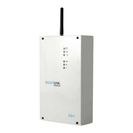
Installation and programming manual Chapter 2 DEVICE DESCRIPTION Unpacking the device The device is packed inside a cardboard box containing: • The SmartLinkAdv comprises a PCB mounted inside a metal box • A bag containing the installation kit comprising: •• Antenna ••... - Page 10 Telephone dialler Metal backbox PCB board Table 2-1: Description of parts Terminal board Battery housing Open-tamper microswitch Wall-mount screw locations Battery connector Screw holes USB connector Cable entries SIM card connector Dislodgement-tamper microswitch location Antenna connector Antenna placement hole Default-data reset button Buzzer Activity LED GSM signal reception LED...
-
Page 11: Signalling From Device
Installation and programming manual Table 2-3: Technical specifications Models SmartLinkAdv/P SmartLinkAdv/G SmartLinkAdv/GP Nominal output 13.8 V ±10% voltage Voltage Functioning range 11 - 16 V standby status 40 mA 100 mA PCB current-draw during transmission 300 mA during maximum 70 mA 600 mA Maximum current draw of +AUX 400 mA... - Page 12 Telephone dialler Table 2-5: LED signalling Status Num. Colour Signalling Slow flashing Fast flashing Operating Device Green Device initializing status operating Flash cycle followed by pause: • 1 flash: general battery fault No faults Fault • 2 flashes: telephone line fault present •...
-
Page 13: Chapter 3 Smartlinkadv Functions
Installation and programming manual Chapter 3 SMARTLINKADV FUNCTIONS Telephone line down management The devices that are to use the reserve line during PSTN line-down conditions must be connected to terminals 15 and 16. When the PSTN line is operating properly, terminals 15 and 16 are connected internally to 17 and 18. -
Page 14: Event Activations
Telephone dialler The outputs can be configured as: • Bistable • Pulse This is an output whose status can be controlled (activated/ CONTROLLED OUTPUT deactivated) and used for other activations. An electrical input point used for the management/control of signals DOUBLE ZONE coming from two devices. -
Page 15: Command And Shortcuts
Installation and programming manual Command and Shortcuts A command is a request from the end-user or a device to the SmartLinkAdv to carry out one or more of its functions. During the programming phase of the SmartLinkAdv you can SHORTCUTS arrange the commands into shortcuts. - Page 16 Telephone dialler 3-6-1 Commands over the GSM network Up to 200 actions can be programmed to activate in response to remote GSM commands. Each of the actions can be triggered by either an SMS command or a Caller ID command or both. Users who wish to activate a command via SMS text must enter the COMMAND VIA SMS command details as follows:...
-
Page 17: Easyscan
Installation and programming manual A Caller ID command is a command requested over-the-phone by INCOMING CALLER ID an end-user whose telephone number is present in the configuration COMMANDS of the actions to be carried out following the command. This type of telephone number must be associated with a user code. -
Page 18: Chapter 4 Installation
Telephone dialler Chapter 4 INSTALLATION Wall-mounting The SmartLinkAdv should be located in a place that is not on view or easily accessible to outsiders. ATTENTION! Verify that the GSM network signal of the selected provider is adequate. Do not install the device near metal objects. Ensure that there are at least two metres between the device and other electrical devices. -
Page 19: Mounting The Antenna
Installation and programming manual ATTENTION! Ensure that the Mains is switched Off during the mains connection phase. Danger of electric shock. Connect the power supply (already connected to the mains) to terminals “+ 14 -” of the PCB (Table 2-2 "Terminals on the terminal board"), taking care to respect the polarity of the electrical wires. -
Page 20: Telephone Connections
Telephone dialler Telephone connections Connect the PSTN line to terminals 17 and 18 (Table 2-2 "Terminals on the terminal board"). Note SmartLinkAdv is protected against eventual lightning strikes. Connect the telephone equipment (or other device/apparatus that requires a reserve telephone line) to terminals 15 and 16. Up to 4 devices can be connected in parallel. -
Page 21: Pc Connection
Installation and programming manual PC Connection For the programming of the SmartLinkAdv, the project and monitoring processes of the system the SmartLinkAdv is connected to requires a connection with a PC equipped with SmartLeague software (refer paragraph 6-1 Using the SmartLeague software program). -
Page 22: Wiring And Balancing Alarm Detectors
Telephone dialler Wiring and balancing alarm detectors The wiring and respective balancing method depend on the type of Gold detector you are installing, and the level of protection you wish to White Orange achieve. The detectors can be powered through: •... - Page 23 Installation and programming manual 4-8-2 Single balancing Single zones can discriminate 3 conditions on the entire terminal: • standby • alarm • tamper (short-circuit) For each of these the SmartLinkAdv reads different values of the equivalent resistance on the terminal, shown below in Ohm: 6K8Ohm Zone...
- Page 24 Telephone dialler 4-8-4 Double-Zone balancing Double zones without EOL resistor can discriminate 5 conditions on the entire terminal: • standby on both zones • alarm on zone 1 and standby on zone 2 • alarm on zone 2 and standby on zone 1 3K9Ohm •...
-
Page 25: Connecting The Outputs
Installation and programming manual Connecting the outputs The SmartLinkAdv can activate one (or more) outputs in response to a recognized event. All the outputs are open-collector outputs capable of sinking a maximum current of 150mA. The wiring diagram below illustrates a series of typical connections for the activation of a load when a Normally Open output closes to GND. -
Page 26: Chapter 5 First Power Up
Telephone dialler Chapter 5 FIRST POWER UP In order to allow the system to perform an accurate auto-enrolling operation on "First power-up", work carefully through the following steps. ATTENTION! When completing the wiring ensure that the power supply sources (mains 230V a.c. and backup battery) to the SmartLinkAdv and its connected devices are disconnected. - Page 27 Installation and programming manual Note The results obtained by the “Easyscan” regarding the GSM signals should not be considered constant throughout time, as they are subject to changes relating to the GSM service. Therefore, you should carry out the Easyscan operation at regular intervals or, at least, when the system is undergoing maintenance.
-
Page 28: Chapter 6 Project Development And Programming
Telephone dialler Chapter 6 PROJECT DEVELOPMENT AND PROGRAMMING The SmartLinkAdv system was designed to allow programming via PC. All the functions relating to programming and the project are accessible through the software program. You will need: • a computer which can be connected to the already-installed SmartLinkAdv. -
Page 29: Using The Software Program
Installation and programming manual Table 6-1: SmartLeague software program - homepage Open solutions bar List of recent solutions - which will allow you create new solutions or open existing solutions Documentation installed on the computer. Area dedicated to help and service via Internet. -
Page 30: Programming Via The Software
Telephone dialler Table 6-2: SmartLeague - solutions The freshly opened template remains in the forefront whilst the other open template and the Homepage remain in the background. Installation tree structure. Section in question. Programming template of the component to be programmed (selected from the tree structure). -
Page 31: Reset Default Settings
Installation and programming manual Select the part of the system you wish to program from the tree menu on the left. Set the parameters in the Programming section on the right. Write the data on the SmartLinkAdv by clicking on the key. - Page 32 Telephone dialler You can reach this section through the Monitoring template which is next to the Programming template, or by selecting Control panel, Monitoring options. The section provides two sub-sections which can be opened by clicking on the header label: •...
-
Page 33: Chapter 7 En50136 Compliance
Installation and programming manual Chapter 7 EN50136 COMPLIANCE SmartLinkAdv series devices are EN 50136-1 and EN 50136-2 compliant. The SmartLeague software program provides preset programming parameters which guarantee 50136-2 standard compliance. activate these preset parameters automatically select Programming, EN50136-2 standard compatibility of SmartLinkAdvanced system. -
Page 34: Access Levels
Telephone dialler Access Levels The standard defines the following access levels to the device and distinct limitations of use of the system: • Level 1 - access by any person (e.g. passer-by) • Level 2 - user access • Level 3 - installer or maintenance operator access (authorized by user - level 2) •... - Page 35 Installation and programming manual Terminal “T2” must manage “Hold-up alarm” and “Fault” signals coming from another two CIE outputs. Therefore, it is necessary to set up a double-zone balance connection with EOL (refer to paragraph 4-8-5 Double balanced zone with EOL) and program terminal T2 as a double zone with the following zone descriptions: •...
-
Page 36: Appendix A Events
Telephone dialler Appendix A EVENTS An event is a condition recognized by the SmartLinkAdv; each event is characterized by an activation (when an event occurs) and a restoral (when the event ends). The following table shows the events the control panel recognizes, the number of events for each type, the trigger and restoral method of each event and whether the event is a pulse event (pulse events restore automatically soon after activation). - Page 37 Installation and programming manual Table 7-3: Event type Name Occurs when... Restores when ... Number of Pulse events events Deep discharge Battery electrically disconnected Battery connected due to deep discharge shutdown The primary 230V a.c. power The primary 230V a.c. power Mains failure source is not present (blackout) source restores...
-
Page 38: Appendix B Declaration Of Conformity
1999/5/EC. Islenska: Hér með lýsir INIM Electronics yfi r því að SmartLinkAdv er í samræmi við grunnkröfur og aðrar kröfur, sem gerðar eru í tilskipun 1999/5/ Italiano: Con la presente, INIM Electronics s.r.l. -
Page 39: Notes
Installation and programming manual Notes... - Page 40 Telephone dialler ISO 9001 Quality Management certified by BSI with certificate number FM530352 Centobuchi, via Dei Lavoratori 10 63076 Monteprandone (AP) ITALY Tel. +39 0735 705007 _ Fax +39 0735 704912 info@inim.biz _ www.inim.biz...
Need help?
Do you have a question about the SmartLink Advanced Series and is the answer not in the manual?
Questions and answers