
Subscribe to Our Youtube Channel
Related Manuals for AIREDALE LogiCool OnRak


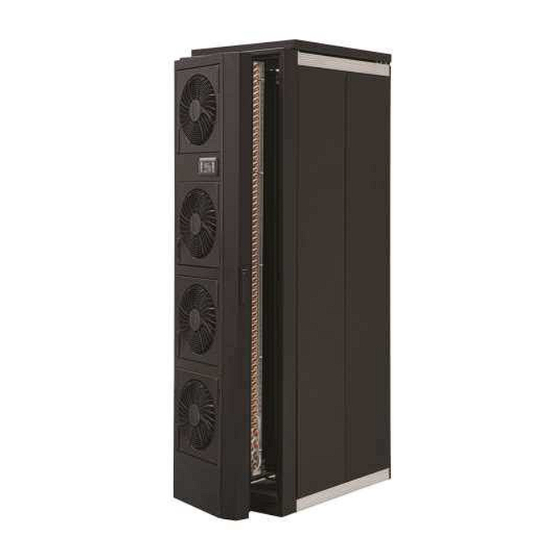
Summary of Contents for AIREDALE LogiCool OnRak
- Page 1 LogiCool OnRak IT Cooling T e c h n i c a l , I n s t a l l a t i o n , O p e r a t i o n a l a n d M a i n t e n a n c e M a n u a l...
-
Page 2: About Airedale Products & Customer Services
The development of Airedale products and services is continuous and the information in this document may not be up to date. It is important to check the current position with AIAC Ltd at the address stated. This document is not part of a contract or licence unless expressly agreed. -
Page 3: Warranty
(excluding costs for any specialist access or lifting equipment that must be ordered by the customer). Any spare part supplied by Airedale under warranty shall be warranted for the unexpired period of the warranty or 3 months from delivery, whichever period is the longer. -
Page 4: Health And Safety
CAUTION Installation, service and maintenance of Airedale equipment should only be carried out by technically trained competent personnel. CAUTION When working with any air conditioning units ensure that the electrical isolator is switched off prior to servicing or repair work and that there is no power to any part of the equipment. -
Page 5: Table Of Contents
IT Cooling LogiCool OnRak CONTENTS About Airedale Products & Customer Services ..............2 Warranty ............................. 3 Health and Safety ........................4 Personal Protective Equipment ....................4 Electrical Bonding ........................4 ....................6 Nomenclature ......................... 6 Introduction ..........................6 Standard Features ......................... 7 Optional Features ........................ -
Page 6: Nomenclature
75%). This configuration greatly increases the energy efficiency ratio (EER) of the equipment. CE Directive Airedale certify that the equipment detailed in this manual conforms with the following EC Directives: 2004/108/EC Electromagnetic Compatibility Directive (EMC) -
Page 7: Standard Features
IT Cooling LogiCool OnRak Standard Features The OnRak unit comes with a series of standard features. Standard Features EC axial fans EC fan node 0-10V 2 or 3 way chilled water valve Advanced Airetronix controls Water temperature sensor Tri coloured LED (Alarm status) for easy fault detection Rack mounted temperature / humidity sensor Leak detection Bleed and drain valves... - Page 8 LogiCool OnRak IT Cooling Rack Mounted Rack mounted temperature and Humidity sensor shall be supplied as standard. This Temperature/ Humidity shall be supplied loose for onsite fitment in a customer rack. Sensor Leak Detection Leak detection for the water system, able to report alarm status to the BMS system shall be provided.
-
Page 9: Optional Features
Remote Handheld Display (unit fitted with RJ11 Connection port) No Display (RJ11 Connection port only) Modbus / Carel BMS The Airedale controllers shall be able to communicate directly using the Modbus® Connection protocol. The Modbus® card shall be a small PCB (60mm x 30mm), which can be plugged into the controller to provide it with the following protocol support Modbus®... - Page 10 Airedale supervisory plug-in cards which make communicating with an Airedale unit simply a matter of logging onto the office Intranet or via the web. Based on Ethernet TCP/IP secure technology, pCOWeb shall require no proprietary cabling.
- Page 11 IT Cooling LogiCool OnRak Dual Power Supply Dual supply for redundancy and backup in the event of mains supply failure shall be provided. The dual power supply switch ensures that the OnRak always has an incoming power supply. For the dual power supplies to operate effectively, the incoming power supplies must have the same voltage and frequency and be within 120°...
-
Page 12: Technical Data
LogiCool OnRak IT Cooling Technical Data IMPORTANT The following information is for general guidance; refer to the certified drawings provided for installation. CAUTION ALL work MUST be carried out by technically trained competent personnel. The equipment contains live electrical and moving parts, ISOLATE prior to maintenance or repair work. -
Page 13: Cooling Performance Lor 6042U-C028-0 (N+1 Configuration, Fans At 75%)
IT Cooling LogiCool OnRak Cooling Performance LOR 6042U-C028-0 (N+1 configuration, Fans at 75%) 45°C SDT 40°C SDT 35°C SDT Water Inlet Temperature °C (based on 6°C T) (1) At the design chilled water temperature project a line until it intersects with the Server Discharge Temperature (SDT), read off the cooling performance. -
Page 14: Cooling Performance Lor 6042U-C033-0 (N Configuration, Fans At 100%)
LogiCool OnRak IT Cooling Cooling Performance LOR 6042U-C033-0 (N Configuration, Fans at 100%) 45°C SDT 40°C SDT 35°C SDT Water Inlet Temperature °C (based on 6°C T) Water Inlet Temperature °C (based on 6°C T) (1) At the design chilled water temperature project a line until it intersects with the Server discharge temperature (SDT), read off the capacity. -
Page 15: Cooling Performance Lor 8042U-C032-0 (N+1 Configuration, Fans At 75%)
IT Cooling LogiCool OnRak Cooling Performance LOR 8042U-C032-0 (N+1 configuration, Fans at 75%) 45°C SDT 40°C SDT 35°C SDT Water Inlet Temperature °C (based on 6°C T) Water Inlet Temperature °C (based on 6°C T) (1) At the design chilled water temperature project a line until it intersects with the Server discharge temperature (SDT), read off the capacity. -
Page 16: Cooling Performance Lor 8042U-C038-0 (N Configuration, Fans At 100%)
LogiCool OnRak IT Cooling Cooling Performance LOR 8042U-C038-0 (N Configuration, Fans at 100%) 45°C SDT 40°C SDT 35°C SDT Water Inlet Temperature °C (based on 6°C T) Water Inlet Temperature °C (based on 6°C T) (1) At the design chilled water temperature project a line until it intersects with the Server discharge temperature (SDT), read off the capacity. -
Page 17: Ethylene Glycol Correction Factors
IT Cooling LogiCool OnRak Ethylene Glycol Correction Factors Calculation of Design The maximum design volumetric flow rate can be calculated using the following equation: Volumetric Flow Rate (l/s) x Cp x T Where: Cooling Capacity (kW). Temperature Difference between Water/Glycol Entering/ Leaving (°C). Density of Glycol/Water mixture at design condition. -
Page 18: Mechanical Data
LogiCool OnRak IT Cooling Mechanical Data LOR6042U-C028-0 LOR6042U-C033-0 LOR8042U-C032-0 LOR8042U-C038-0 Dimensions - H x W x D 2030 x 600 x203 2030 x 600 x 203 2032 x 800 x 213 2032 x 800 x 213 Weight - Machine Operating Construction Sheet steel, epoxy baked powder paint Material/ Colour... - Page 19 IT Cooling LogiCool OnRak Coil, Hose and Valve Pressure Drop Only IT Cooling Technical, Installation and Maintenance Manual :6912497 V1.8.0 _08_2014...
-
Page 20: Dimensional Data
LogiCool OnRak IT Cooling Dimensional Data Dimensions LOR 600 2030 LOR 800 2032 Component Masses LOR 600 LOR 800 Door Mating frame Fans IT Cooling Technical, Installation and Maintenance Manual :6912497 V1.8.0_08_2014... -
Page 21: Sound Measurement Method
IT Cooling LogiCool OnRak Sound Measurement Method Measurement of Sound All sound data quoted has been measured in the third-octave band limited values, Data using a real time analyser calibrated sound intensity meter in accordance with BS EN ISO9614 Part 1: 1995. All sound power levels quoted are calculated from measured sound intensity according to BS EN ISO9614 Part 1: 1995. -
Page 22: Pipework Schematics
LogiCool OnRak IT Cooling Pipework Schematics Scheme 1 3 way chilled water valve Bypass balancing valve Normally closed solenoid valves Threaded pipe connections Scheme 2 3 way chilled water valve Bypass balancing valve Normally closed solenoid valves Quick connector IT Cooling Technical, Installation and Maintenance Manual :6912497 V1.8.0_08_2014... - Page 23 IT Cooling LogiCool OnRak Pipework Schematics Scheme 3 2 way chilled water valve Normally closed solenoid valves Threaded connections Scheme 4 2 way chilled water valve Normally closed solenoid valves Quick connector IT Cooling Technical, Installation and Maintenance Manual :6912497 V1.8.0 _08_2014...
-
Page 24: Installation
CAUTION Airedale will accept no responsibility for mishandling during the positioning of the equipment. The data rack must be mounted level. Ensure that the OnRak, the mating frame and data rack are earth bonded together. -
Page 25: Data Rack Feet
IT Cooling LogiCool OnRak Fitting Hinges The OnRak needs to be lifted vertically to ensure that the assembly fits onto the hinges. Care must be taken whilst locating the lift-off hinges together prior to lowering into place. Illustrations for guidance only Data Rack Feet The data rack feet must be used prior to the unit being mounted to the rack. -
Page 26: Rack Support Wheel
LogiCool OnRak IT Cooling Rack Support Wheel A support wheel is provided for fitment under the Onrak door. This is to be at the same level as the door rack feet. The wheel is to be fitted ensuring that it has free movement. Wheel Adjustment The castor can be adjusted by the following procedure Slacken locking nut... -
Page 27: Door Latch Mechanism
IT Cooling LogiCool OnRak Door Latch Mechanism CAUTION Ensure that the door latch mechanism does not snag on the sheet metal. Distortion of the door can occur if the latch is forced IT Cooling Technical, Installation and Maintenance Manual :6912497 V1.8.0 _08_2014... -
Page 28: Floor Cut Outs
LogiCool OnRak IT Cooling Floor Cut Outs To enable the flexible pipework installation the following minimum cut out is required in the floor tile below the unit. Contact your grommet supplier for exact sizes. This ensures that the pipework does not get obstructed causing additional strain on the fittings. -
Page 29: Water Connections
IT Cooling LogiCool OnRak Water Connections Two flexible, stainless steel braided hoses connect the coil to the chilled water supply. The flexibility of the hoses allows the OnRak door to be easily opened for accessing hardware within the server cabinet, without the need to disconnect services or disrupt cooling.. -
Page 30: Flexible Water Connection
LogiCool OnRak IT Cooling Flexible Water Connection Pipework Sweep The stainless steel braided must be installed so that the hose has unobtrusive movement in either fully opened or closed positions Plan View Side View Recommended Dimensions X = Floor Void Depth Y = 500mm Z = 110mm Minimum recommended hose length X + 1m... -
Page 31: Compression Fittings
This ensures that the pipe does not become soft. If the pipe gets soft the olive cannot compress onto the pipe. Airedale will not be held responsible for any water leaks by compression fitting misuse. -
Page 32: Chilled Water Valve (2+3 Way)
LogiCool OnRak IT Cooling Chilled Water Valve The chilled water valve has an indication of flow on the stem. The actuator is securely attached to the top of the valve so that when there is a demand for cooling the valve (3 Way) opens allowing water to flow through the coil. - Page 33 IT Cooling LogiCool OnRak Chilled Water Valve The chilled water valve has an indication of flow on the stem. (2 Way) The actuator is securely attached to the top of the valve so that when there is a demand for cooling the valve opens allowing water to flow through the coil. No demand, the water is shut off allowing no water to enter the coil (0 VDC no demand, 10 VDC 100% demand).
-
Page 34: Solenoid Valve
Coil Water Connections Swivel pipework connection to coil Coil connections are brazed at Airedale. Full pressure testing to 20Barg is carried out prior to unit despatch. Water Temperature Sensor The water temperature sensor is attached to the inlet water pipework with a copper strap. -
Page 35: Customer Terminal Box
IT Cooling LogiCool OnRak Customer Terminal Box The customer terminal box is attached to the coil guard during shipment. Carefully remove this and feed the box through the hole in the mating frame and floor tile cut-out. This must be done after the door is fitted to the mating frame. Dual Power Supply The dual power supply can be either fitted into a rack or fitted in the floor void under the server rack. - Page 36 LogiCool OnRak IT Cooling Attach the earth strap to the rear of the power supply unit. Locate the Dual power supply between the cable support guides of the server rack. Secure the unit with screws supplied by your rack manufacturer. Attach the incoming fused power supplies.
- Page 37 IT Cooling LogiCool OnRak Under Floor Dual Power The under floor Dual Power supply is located under the floor void. The supply is to be Supply mounted securely. Provision is made for fixing to the floor or associated supports. Attach relevant earth bonding to the power supply. Attach the incoming fused power supplies.
-
Page 38: Rack Mounted Temperature / Humidity Sensor
LogiCool OnRak IT Cooling Uninterrupted Power The UPS shall fit within the server cabinet and shall be the same dimension as 1U/ 2U Supply rack. Various capacities are available. Installation of the UPS is rack mounted. Full information of the installation is supplied with the UPS. The UPS can be personalised to the application (response times etc) through a computer. -
Page 39: Rack Pressure Management
IT Cooling LogiCool OnRak Rack Pressure The rack pressure management comes in two parts for onsite fitment. Management Part one (Factory Fitted) A static pressure ring (Negative pressure) is fitted behind the coil guard. An airflow tube comes out from the controller and is then routed around the drip tray. (Negative Pressure (Within... -
Page 40: Rack Sealing
LogiCool OnRak IT Cooling Rack Sealing The rack must be sealed so that air does not bypass the servers. The racks must not have any ventilation holes such as a perforated roof. Any space within the server racks that are redundant must be sealed with blanking panel (usually supplied in 1U and 2U). -
Page 41: Interconnecting Wiring
Volt Free Common Alarm Non Critical Alarm Volt Free Alarm N/O RX-/Tx- Use Awg20/22 twisted pair (with overall shield) cable, Belden ref. 8762 (Airedale ref: 6110316), or equivalent, for RX+/Tx+ Network Connections (Inward connection) network RX-/Tx- Use Awg20/22 twisted pair (with overall shield) cable, Belden ref. -
Page 42: Automatic Fan Disconnect
LogiCool OnRak IT Cooling Automatic Fan Disconnect This type of connector removes the requirement for manual disconnection of the fan wiring, as removing the Plug fan automatically and fully disconnects power from the (Fan side) fan. Socket (Unit side) IT Cooling Technical, Installation and Maintenance Manual :6912497 V1.8.0_08_2014... -
Page 43: Controls
IT Cooling LogiCool OnRak Controls Addressing the Display Keypad The address of the display keypad can be configured only after having connected the power supply, using the RJ11 connection cable. To access configuration mode, press the buttons together and hold them for at least 5 seconds; the screen shown below will be displayed, with the cursor flashing in the top left corner: To change the address of the display keypad (display address setting), press the button once: the cursor will move... - Page 44 LogiCool OnRak IT Cooling When more than one alarm is active the ALARM button will illuminate red. Pressing the ALARM button once will indicate information regarding any ALARM active alarms. Pressing the ALARM button twice will reset any active alarms. Pressing the PRG button will select the main navigation menu.
-
Page 45: Extra Functions Buttons
IT Cooling LogiCool OnRak Extra Functions Buttons UP + DOWN+ Allow users to change display address. ENTER ALARM + Allows access to controller system information. ENTER ALARM + Allows access to change controller address (only when display address is zero) ESC + Allows the user to switch between the preinstalled languages ENTER... -
Page 46: Enabling The Unit
LogiCool OnRak IT Cooling Enabling the Unit To turn the unit on press the key to enter the program menu. Using the keys select the Unit On/Off option and press When is pressed the above screen will be shown. To turn the unit on simply press the key again and the screen will change: Once the screen has changed to the above, press the... -
Page 47: Dew Point Control
IT Cooling LogiCool OnRak Dew Point Control The pCO controller within the OnRak unit can calculate the dew point within a room by monitoring the temperature and humidity of that room and then performing a calculation to provide a dew point value. The pCO controller uses a signal received from the temperature/humidity sensor which is wired into the controller. -
Page 48: Temperature Sensor Locations
LogiCool OnRak IT Cooling Temperature Sensor Locations Air Off Temp. Sensor No. 1 Server Air Off / Coil On Sensor No. 1 Air Off Temp. Sensor No. 2 Server Air Off / Coil On Sensor No. 2 Air Off Temp. Room Temp. -
Page 49: Modes Of Operation
IT Cooling LogiCool OnRak Modes of Operation Temperature Neutral Mode Server Temperature Sensors regulate the fan speed to maintain a constant cabinet Heat lost to air temperature of 40°C Air Off Temp. Sensor No. 1 Server Air Off Sensor No. 1 Air Off Temp. -
Page 50: Load Neutral Mode
LogiCool OnRak IT Cooling Load Neutral Mode Server Temperature Sensors regulate the fan speed to maintain a constant cabinet temperature of 40°C Heat lost to air Remote Room Air Temperature Server Sensor Air Off Sensor No. 1 ROOM AIR TEMP Server Air Off Sensor... -
Page 51: Rack Pressure Management
IT Cooling LogiCool OnRak Rack Pressure Management range. However, if the pressure within the server space changes beyond the high or low differential set-points, the fans prioritise pressure control to bring the server pressure back within limits, at which point normal temperature control resumes. -
Page 52: Commissioning Procedure
To be read in conjunction with the commissioning sheets provided. Please ensure all documents have been completed correctly and returned to CAUTION Airedale technical support to validate warranty. All work MUST be carried out by Technically Trained and competent personnel. CAUTION The equipment contains live electrical and moving parts, Isolate prior to maintenance or repair work. - Page 53 IT Cooling LogiCool OnRak Commissioning Procedure Fan Removal Alarm Check alarm state when a fan goes offline. Differential Pressure The differential pressure switch should cause the OnRak fans to increase / decrease when the server fans are active. One of the fans can be removed to allow the differential pressure to be recognised if the server load is low.
-
Page 54: Maintenance
LogiCool OnRak IT Cooling Maintenance Changing EC Fans hot swa without the need to disconnect the power from the entire unit. Removing the 4 security fixings enable the fan to be removed The unit has automatic disconnect sockets to the fan motors. The remaining fans will increase speed to compensate for the fan being serviced (only in N+1 configuration) CAUTION The unit will remain live up to the fan disconnect socket. -
Page 55: Operational Maintenance Checks
IT Cooling LogiCool OnRak Operational Maintenance checks Owners Responsibility To ensure that the unit can be maintained correctly the following requirements are required. Maintain a safe working environment around the unit, free from obstructions and debris. The unit shall follow the following maintenance regime as a minimum. The equipment contains live electrical and moving parts, ISOLATE prior to maintenance or repair work. -
Page 56: Troubleshooting
LogiCool OnRak IT Cooling Troubleshooting FAULT POSSIBLE CAUSE REMEDY/ACTION Unit will not start No power Check power supply to the controller. Wired incorrectly Check wire connections in accordance with wiring diagram on control panel. Loose wires Check all wires, connections, terminals etc. Fan not operating - power Power supply failure Check power supply at circuit breaker. - Page 57 IT Cooling LogiCool OnRak IT Cooling Technical, Installation and Maintenance Manual :6912497 V1.8.0 _08_2014...
- Page 58 LogiCool OnRak IT Cooling IT Cooling Technical, Installation and Maintenance Manual :6912497 V1.8.0_08_2014...
- Page 59 IT Cooling LogiCool OnRak IT Cooling Technical, Installation and Maintenance Manual :6912497 V1.8.0 _08_2014...
- Page 60 Head Office: Airedale International Air Conditioning Ltd Leeds Road Rawdon Leeds LS19 6JY United Kingdom Tel: +44 (0) 113 239 1000 Fax: +44 (0) 113 250 7219 e-mail: enquiries@airedale.com website: www.airedale.com PART NO: ISSUE (TM E) 12/2009 V1.1.0 11/2010 12/2010 V1.3.0...
Need help?
Do you have a question about the LogiCool OnRak and is the answer not in the manual?
Questions and answers